Choosing a single phase vs three phase voltage protector starts with the actual supply and the load, not the enclosure width or a headline current rating. Verify which voltages the device monitors, which conductors its output controls and which fault conditions it detects. A three-phase installation can include single-phase loads, and a three-phase motor can require functions beyond overvoltage and undervoltage detection. Match the exact product to the circuit diagram and equipment instructions. Do not confuse a sustained-voltage protector with a surge protective device, voltage regulator, motor overload relay or safe-isolation device.
Identify the circuit before comparing products
Record the supply arrangement, nominal voltage, frequency, conductor functions and earthing arrangement from the approved installation documents. Determine whether the load uses phase-to-neutral supply, phase-to-phase supply or a complete three-phase circuit. A label such as single phase does not by itself tell a buyer whether a neutral is present or which conductors require control. Use the circuit documentation instead of inferring the arrangement from a country name or a photograph of the panel.
For a mixed distribution board, inventory the individual circuits. Some loads may use one phase and neutral while other equipment uses all three phases. Protecting a single branch against its own unacceptable voltage is a different objective from supervising the supply to a three-phase machine. Decide whether a fault on one monitored quantity should interrupt only that branch or prevent the entire machine from running. That decision belongs in the design requirements before the device is selected.
Separate sensing from switching
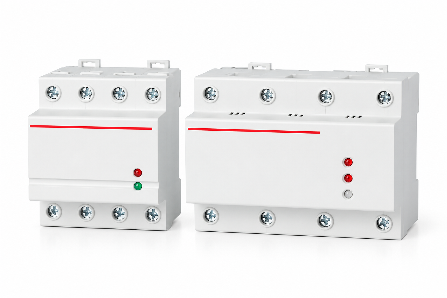
A sensing function measures a defined electrical quantity. An output function either carries a load directly or supplies a control signal to another switching device. The number of visible terminals does not prove the sensing coverage or the supported output duty. Ask for the product circuit, terminal identification and operating description. Confirm whether the device senses all required phases, needs a neutral reference and directly switches the load or controls a contactor.
If a monitoring relay operates a contactor, review the complete chain. The relay's output rating needs to match the contactor control duty, while the contactor must match the load's switching duty and installation requirements. A small relay output rating is not the same as the contactor's load rating. Likewise, a directly switching protector's marked current should not be assumed to cover every motor starting or switching condition. Obtain the exact application evidence rather than combining unrelated ratings.
Check the required fault functions individually
Overvoltage and undervoltage supervision concern the declared monitored voltages and thresholds. Phase loss, phase sequence and voltage imbalance are separate functions. A product described as three phase may not provide all of them. List each required fault condition in the enquiry and ask the supplier to confirm its detection, output action, recovery behavior and relevant limitations. Treat an unlisted function as unconfirmed, even if another product in the same range includes it.
Phase sequence matters only where the equipment's operation depends on it, and the equipment instructions determine the consequence of an incorrect sequence. Voltage imbalance is also different from all three phases being too low. The US Department of Energy motor-systems resources provide background for evaluating motor performance and supply conditions. Use them as engineering context, while applying the exact motor, drive and installation documentation to the final protection design.
Compare the configurations with an evidence table
| Question | Single-phase branch review | Three-phase equipment review |
|---|---|---|
| Supply | Actual phase-to-neutral or phase-to-phase arrangement | Complete phase and neutral requirements |
| Sensing | Declared monitored voltage | All required voltages and fault functions |
| Output | Direct load or control duty | Coordinated load interruption or control duty |
| Other functions | Equipment-specific requirements | Phase loss, sequence and imbalance individually confirmed |
| Recovery | Branch and load restart sequence | Machine and interlock restart sequence |
The table compares review questions, not guaranteed features of every device. A single-phase protector can be the appropriate choice for an individual branch in a three-phase building. A three-phase monitoring function can be appropriate for a machine that must stop when one required phase condition becomes unacceptable. Neither arrangement should be chosen simply because one product has more poles or a larger enclosure.
Purchasing teams should retain the answers with the final circuit diagram. If a quotation says suitable for three phase without explaining the monitored quantities and output arrangement, ask for clarification. This avoids discovering during commissioning that the device supervises only one quantity, uses an unavailable neutral or cannot drive the proposed control circuit. It also prevents a visually similar substitute from changing the system's intended behavior.
Review neutral and conductor responsibilities
A neutral, protective conductor and combined conductor have different functions. The designer must determine the permitted arrangement and switching requirements under the installation's adopted rules. A generic multi-pole illustration should not become a wiring instruction. Confirm conductor identification, terminal roles and the exact product connection diagram with qualified personnel before approving the installation.
Never interpret the output-open indication as proof that every relevant part is isolated. The device may depend on supply that remains energized, and another source may exist in the installation. The HSE publication on safe electrical working practices provides general context for planning electrical work and establishing safe conditions. It does not approve a particular pole arrangement or replace the site's isolation procedure. Keep operational voltage protection and maintenance isolation as distinct requirements.
Account for motor and drive loads
For a three-phase motor, collect the motor and controller documentation as well as the supply details. Determine which functions are already present in the drive, starter or motor protection equipment. Adding an external voltage protector should support the approved control design rather than create competing recovery commands. Review how a trip is reported, which device removes power and what conditions permit the motor to restart.
A variable-speed drive changes the questions further. Its incoming supply supervision, control-power behavior, fault memory and restart settings can affect the complete response. A downstream illustration of a motor does not prove that a particular protector can be inserted at any point in the system. Follow the drive manufacturer's approved arrangements. If the proposed device switches supply directly, confirm the implications for the drive and the equipment sequence before purchase.
Coordinate recovery across the installation
Automatic reset means a device can restore its output under documented conditions. It does not establish that every connected machine may restart automatically. A three-phase monitor and a contactor circuit may need a separate acknowledgement, interlock or machine-control decision. A single-phase branch can also supply equipment whose restart needs assessment. State the required recovery sequence in functional terms, including what the operator should observe.
For a distribution board with several protected branches, consider the effect of simultaneous recovery. Restoring multiple loads at once can create a different operating condition from restoring one circuit. An engineer should review the start sequence and the supply's capability using actual load information. Do not assume three independent single-phase protectors reproduce the behavior of a coordinated three-phase control system. Separate branch devices can restore at different times and need a design review where the loads are interdependent.
Review the actual SUTON product family
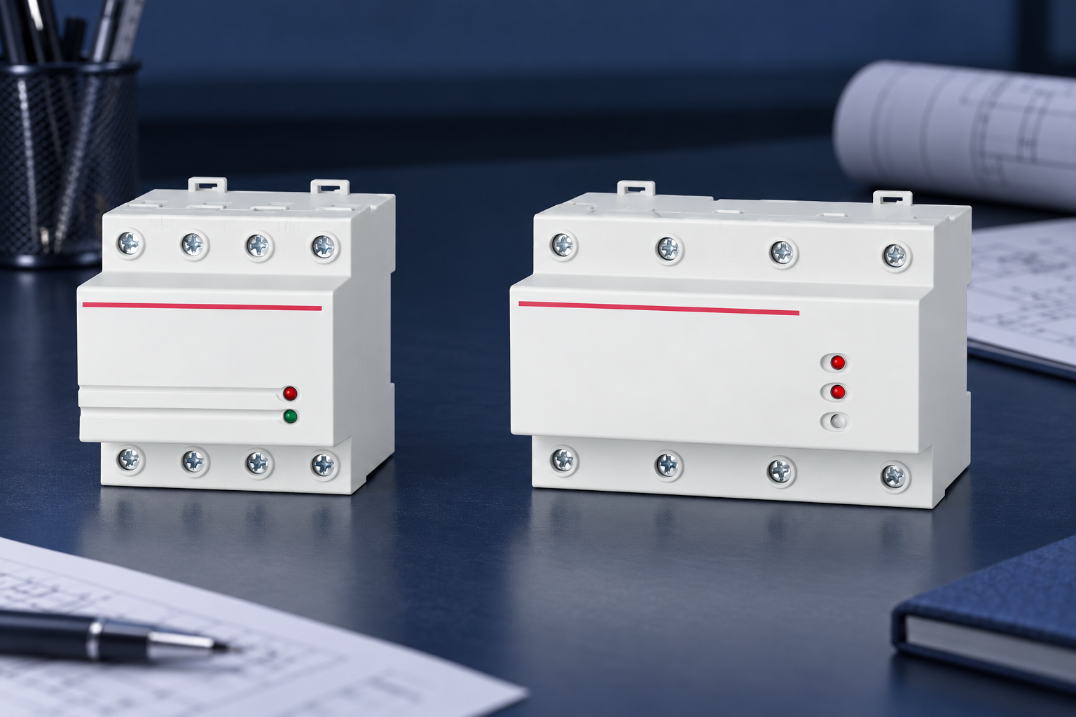
The SUTON DZ47-125V1 automatic-reset voltage protector provides a relevant product reference for procurement discussions. The illustrated exterior is not evidence of phase-loss detection, phase-sequence protection, adjustable thresholds or a particular motor duty. Ask SUTON for the exact variant's current documentation and a confirmed fit to the proposed supply and load. Do not infer functions from the indicator count or the family name.
Use the automatic-reset protector overview for the general function distinction. For timing questions, consult the response-time and accuracy review and the reconnection-delay selection guide. These topics help define the enquiry but do not replace model-specific evidence. A quotation should connect each required function to a documented device behavior.
Verify the proposed configuration before handover
Prepare a controlled acceptance plan that names the equipment, monitored quantities, output endpoints and expected response. Where the requirement includes phase loss, phase sequence or imbalance, specify each as a distinct acceptance item using an approved method. A successful ordinary power-up test demonstrates only that event; it does not prove every fault function. Do not create faults on occupied live machinery to see whether a device reacts.
The HSE guidance on work with electrical equipment provides broader context for planning electrical work. Qualified personnel must follow the exact equipment instructions and site procedures. Record what was tested, the result and any excluded conditions. Retain drawings and setting records so a future replacement can be checked against the actual design rather than selected solely by nominal voltage and current.
Send a complete purchasing enquiry
Include the supply diagram, required sensing functions, load description, control-power arrangement, expected output duty and restart sequence. Identify relevant environmental and enclosure requirements from the project specification. Ask for current instructions, dimensional information, connection details and written confirmation of the proposed application. If any function remains uncertain, record the gap before accepting a substitution or releasing an order.
During handover, explain which fault causes interruption, how it is indicated and who is authorized to restore or change the configuration. Keep spare-device records tied to the exact approved variant. A future product with the same enclosure size may have different sensing or recovery behavior. Reviewing those differences preserves the installation's function and makes troubleshooting clearer when a branch or machine remains unavailable after supply returns.
Frequently asked questions
Can a single-phase protector be used in a three-phase building?
It can be appropriate for an individual single-phase branch when its documented supply, sensing and output duty match that branch. It does not by itself supervise all conditions required by a three-phase machine. The installation design determines the needed arrangement.
Does a three-phase voltage protector always detect phase loss and phase sequence?
No. These are separate functions that need explicit confirmation in the exact product documentation. Ask for the monitored quantities, fault conditions, output action and recovery behavior. Do not infer the features from enclosure width or terminal count.
Are three single-phase protectors equivalent to one three-phase monitor?
Not automatically. They can sense and restore separate branches independently, while a machine may require coordinated supervision and interruption. Qualified designers should review the full circuit and restart behavior before treating either arrangement as equivalent.
Educational video
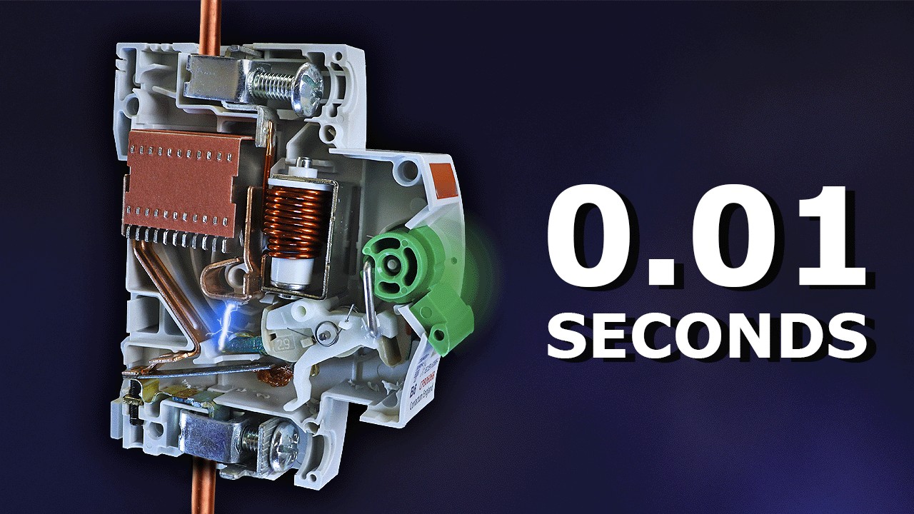
Why Circuit Breakers DON'T Protect People (electric shocks) by The Engineering Mindset. This video explains electrical-shock protection limits; it supports the safety-function distinction here, not an exact SUTON rating, protector response time, feed direction, fuse selection or maintenance procedure.