

Product Overview
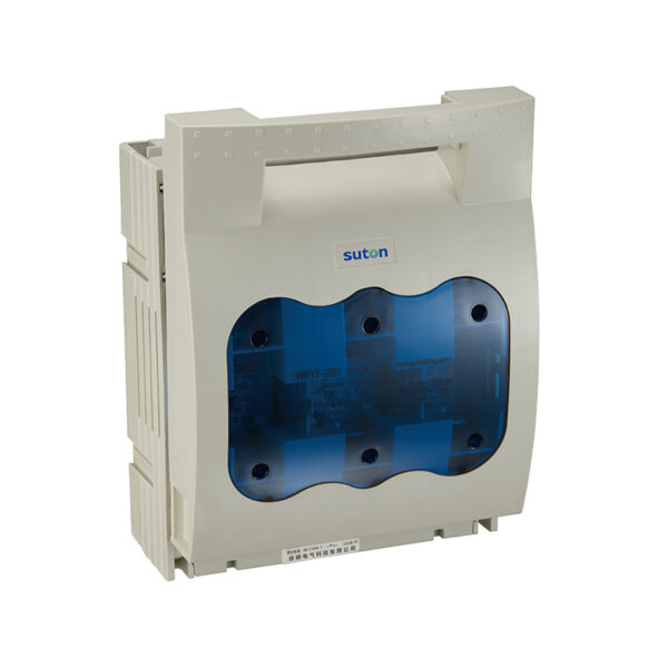
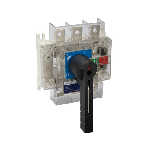
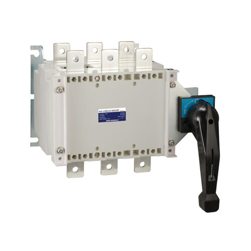
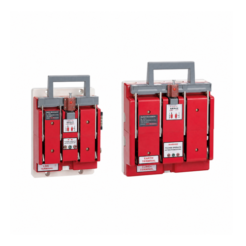
The HR17 series fuse-type isolating switches are capable of on-load operation and are suitable for rated currents ranging from 40 A to 630 A They feature top and bottom input/output configurations, with blade. type terminals and arc-extinguishing devices; the switch housing is fitted with sealed inspection ports at regular intervals, and incorporates built-in signal switches and test switches. A fuse monitor is available as an option, and the switches can also be used as knife switches
The switches feature an attractive, innovative and streamlined design,
and comply with the lEC 60947-3 and GB/T 14048.3 standards.
Model numbers and their meanings
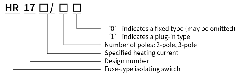
Outline and installation Dimensions(mm)
HR17-40~630A Stationary
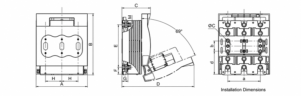
| Model | Pole count | Dimensions (mm) | Installation dimensions (mm) | |||||||||||
| A | B | C | D | E | F | G | H | M | a | b | Φc | d | ||
| HR17-40 | 2 Pole | 56 | 116 | 76 | 150 | – | – | – | – | M7 | 25 | – | Φ6 | – |
| 3 Pole | 77 | 116 | 76 | 150 | – | – | – | – | M7 | 44 | – | Φ6 | – | |
| HR17-100 | 2 Pole | 74 | 121 | 76 | 150 | – | – | – | – | M7 | 31 | – | Φ6 | – |
| 3 Pole | 105 | 121 | 76 | 150 | – | – | – | – | M7 | 62 | – | Φ6 | – | |
| HR17-160 | 3 Pole | 111 | 202 | 83 | 205 | 116 | 24 | 17 | 36 | M8 | 66 | 25 | Φ7 | 70 |
| HR17-250 | 3 Pole | 185 | 247 | 110 | 295 | 185 | 14.5 | 22.5 | 57 | M10 | 114 | 50 | Φ11 | 82 |
| HR17-400 | 3 Pole | 211 | 290 | 125 | 340 | 210 | 25.5 | 26 | 65 | M10 | 130 | 50 | Φ11 | 105.5 |
| HR17-630 | 3 Pole | 256 | 300 | 145 | 360 | 210 | 34 | 30 | 81 | M12 | 162 | 50 | Φ11 | 114 |
| HR17-630/B | 3 Pole | 166 | 288 | 128 | 335 | 125 | 26 | 30 | 44 | M10 | 120 | 50 | Φ11 | 106 |
Key Technical Specifications
| HR17-40 | HR17-100 | HR17-160 | HR17-250 | HR17-400 | HR17-630 | HR17-630/B | ||||||||||||
| Electrical Specifications-tions | With a fuse | Rated operating voltage | Ue | V | AC380 | AC380 | AC400 | AC400 | AC400 | AC400 | / | |||||||
| Rated operating current | Ie | A | 40 | 100 | 160 | 250 | 400 | 630 | / | |||||||||
| Rated insulation voltage | Ui | V | 690 | 690 | 690 | 690 | 690 | 690 | / | |||||||||
| Conventional heating current | Ith | A | 40 | 100 | 160 | 250 | 400 | 630 | / | |||||||||
| Rated impulse withstand voltage | Uimp | kV | 4 | 4 | 8 | 8 | 8 | 8 | / | |||||||||
| Rated short-circuit current limit | Iq | kA | 50 | 50 | 50 | 50 | 50 | 50 | / | |||||||||
| Level of use | AC-21B | AC-21B | AC-23B (AC400)/AC-21B(AC690) | |||||||||||||||
| Number of electrical life cycles | time | 300 | 300 | 200 | 200 | 200 | 200 | / | ||||||||||
| With separating blade | Rated operating voltage | Ue | V | / | / | AC380 | AC380 | AC400 | AC400 | AC400 | ||||||||
| Rated operating current | Ie | A | / | / | 160 | 250 | 630 | 630 | 630 | |||||||||
| Rated insulation voltage | Ui | V | / | / | 690 | 690 | 1000 | 1000 | 1000 | |||||||||
| Conventional heating current | Ith | A | / | / | 160 | 250 | 630 | 630 | 630 | |||||||||
| Rated impulse withstand voltage | Uimp | kV | / | / | 8 | 8 | 12 | 12 | 12 | |||||||||
| Rated short-time withstand current | Icw | kA/1s | / | / | 8 | 10 | 15 | 15 | 15 | |||||||||
| Level of use | / | / | AC-21B | AC-21B | AC-23B | AC-23B | AC-23B | |||||||||||
| Number of electrical life cycles | time | / | / | 200 | 200 | 200 | 200 | 200 | ||||||||||
| Common Parameters | Rated frequency | Hz | 50/60 | 50/60 | 50/60 | 50/60 | 50/60 | 50/60 | 50/60 | |||||||||
| Pole count | 2 | 3 | 2 | 3 | 3 | 3 | 3 | 3 | 2 | 3 | ||||||||
| Fuse | Sizes(RT16/NT/NH) IEC 60269-2 GB/T 13539.2 | 00 | 1 | 2 | 3 | / | ||||||||||||
| Operating current | In | A | 40 | 100 | 160 | 100 | 250 | 200 | 400 | 315 | 630 | 500 | / | |||||
| Power consumption | P | w | / | 5.5 | 12 | 12 | 18 | 32 | 28 | 45 | 45 | 50 | / | |||||
| Organisation | Mechanical life | time | 1700 | 1700 | 1400 | 1400 | 800 | 800 | 800 | |||||||||
| Protection rating | Front | ON: IP20/OFF: IP30 | ||||||||||||||||
| Other | Switch ON/OFF Status Feedback (Micro Switch) | / | / | Optional | Optional | Optional | Optional | Optional | ||||||||||
| Working conditions | Ambient air temperature | ℃ | -5~+40 | |||||||||||||||
| Rated duty cycle | Uninterrupted Duty | |||||||||||||||||
| Operating Instructions | Handle Operation | |||||||||||||||||
| Installation Methods | Vertical Mounting | |||||||||||||||||
| Altitude | m | ≤ 2000 | ||||||||||||||||
| Installation Categories | III、IV | |||||||||||||||||
| Pollution level | 3 | |||||||||||||||||
| Transport and Storage | ℃ | -25~+55 | ||||||||||||||||
Terinal block accessories
| Terminal Dimensions | Terminal type | Torque N*m | Cable Cross-Sectional Area mm² | Compatible Switch Models |
| M8 Bolt (with Cable Lug) | 12-15 | 16-70 | HR17-160 | |
| M10 Bolt (with Cable Lug) | 30-35 | 25-150 | HR17-250~400 | |
| M12 Bolt (with Cable Lug) | 35-40 | 25-240 | HR17-630 | |
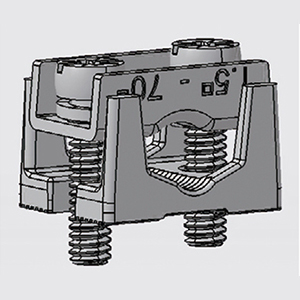 |
ET54224 | 3 | 16-70 s(r) 16-70 s(s) 16-70 f+AE |
HR17-160 |
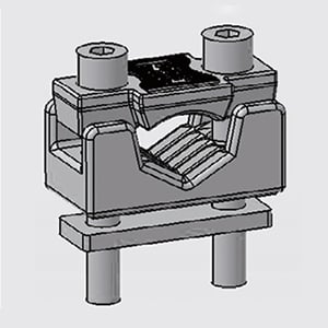 |
ET54207 | 6 | 75-150 s(r) 75-150 s(s) 75-150 f,f+AE |
HR17-250 |
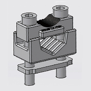 |
ET54208 | 8 | 50-240 s(r) 50-240 s(s) 50-240 f,f+AE |
HR17-400~630 |
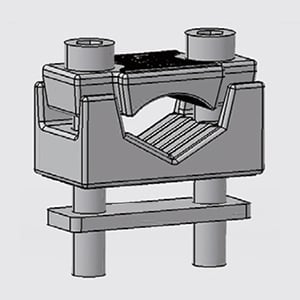 |
ET54209 | 8 | 150-300 s(r) 150-300 s(s) 150-300 f,f+AE |
HR17-630 |
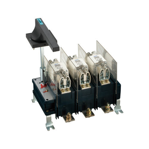
Reviews
There are no reviews yet.