


AFDD electronic loads require a circuit-specific review before a device is selected for the final circuit. List the actual power supplies, LED drivers, chargers, inverters and variable-speed equipment, then check normal switching behavior, source direction, neutral routing and the AFDD manufacturer’s instructions. The aim is to keep arc-fault protection effective while understanding ordinary load signatures and other trip functions. No generic AFDD photograph or “anti-nuisance” claim proves compatibility with every device. Confirm the exact model and document representative commissioning conditions in the approval record.
List the electronic loads before choosing a device
Start with the actual equipment: LED drivers, switch-mode power supplies, inverter appliances, speed-controlled motors, chargers, computers, dimmers and control units. Record the manufacturer and model, normal current, inrush behavior, switching pattern and any built-in filters. The list helps the AFDD supplier understand normal operation on the final circuit. It should not be turned into a blanket rule that electronic equipment is incompatible with arc protection.
Mark which loads operate together and which are added only occasionally. A single office circuit may carry many small supplies whose combined behavior differs from one appliance. A dwelling circuit may change over time as occupants replace equipment. Keep the load list and the AFDD decision with the circuit schedule so later changes can be compared against the original assumption.
Understand normal signatures and hazardous arcs
AFDDs analyze electrical waveforms for signatures associated with dangerous arcing. Normal switches, some motors and power electronics can also create high-frequency activity, so the device must distinguish normal operating events from faults within its declared design. The IET AFDD explanation describes this principle. The IET’s AFDD questions and answers discusses ordinary switching and motor-related arcs as examples of operating activity that should be considered during selection.
Do not assume a catalogue statement such as “anti-nuisance” proves compatibility with every possible electronic load. Ask for the exact model documentation and any application notes covering the equipment in the circuit. If the manufacturer has not evaluated an unusual load combination, state the uncertainty and agree on a commissioning observation plan rather than claiming guaranteed behavior.
| Load characteristic | Selection question | Evidence to collect |
|---|---|---|
| Switch-mode supply | What switching and filter behavior occurs in normal use? | Equipment model and input data |
| Variable-speed motor | What happens at start, speed change and braking? | Operating sequence and manufacturer notes |
| Multiple LED drivers | Can several units start or dim together? | Driver count, controls and load schedule |
| Charger or inverter | Can power flow or source mode change? | Single-line and line/load diagram |
| Mixed socket circuit | Which future appliances may be connected? | Owner use case and maintenance plan |
The table organizes questions. It does not declare any load compatible with a particular AFDD without model-specific evidence.
Match the AFDD configuration to the circuit
Check voltage, frequency, rated current, poles, neutral path, line/load markings, short-circuit capacity and any combined overcurrent or residual-current function. IEC 62606 covers AFDD product types for household and similar AC circuits, including standalone, integrated and declared paired arrangements. It does not establish that one SUTON model works with every electronic power supply. The exact product code and installation sheet control.
For a paired AFDD and MCB or RCBO, record the approved combination and which unit provides each protective function. If the circuit needs residual-current protection, specify its type and sensitivity from the installation study. Avoid treating an AFDD as a replacement for conductor protection or fault-current interruption. The AFDD combination guide explains the arrangements.
Check neutral, earthing and supply direction
Trace all live conductors through the declared sensing path, confirm the neutral connection, and identify any shared returns. An integrated RCBO can trip for a residual-current wiring error, which may be misreported as an arc event. Check the exact status indication before assigning a cause. The neutral wiring guide discusses return-path mistakes relevant to combined protection.
If a circuit has a PV inverter, battery system, generator or transfer switch, draw normal and alternate modes. Some electronic protective devices have direction-sensitive connections, so ask the AFDD manufacturer whether supply can be applied at the nominal load terminals. The IET guidance on bidirectional protective devices explains why this question matters. Do not assume that a test button working in one mode proves the device is suitable for every source mode.
Use the real SUTON product as a reference, not a guarantee
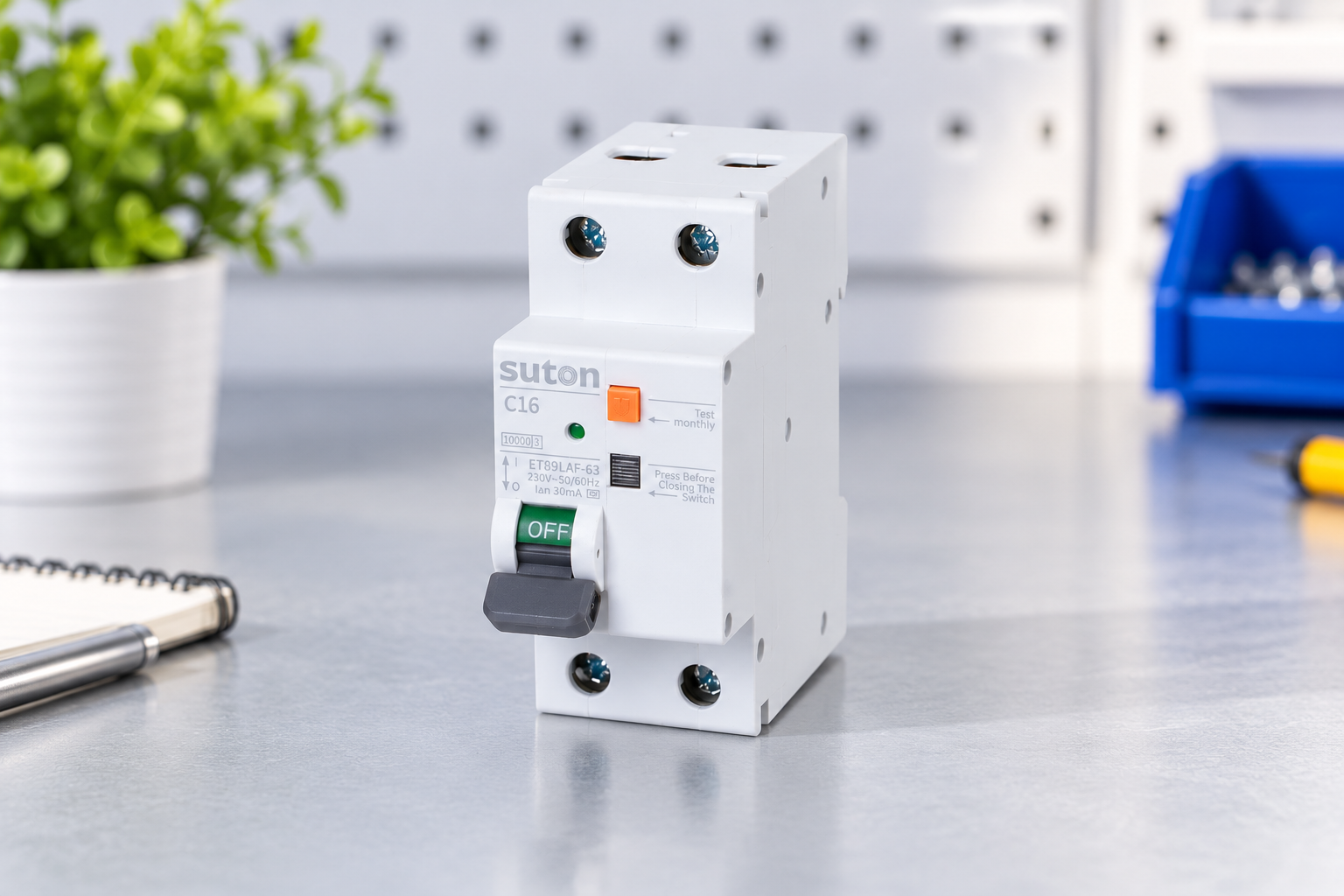
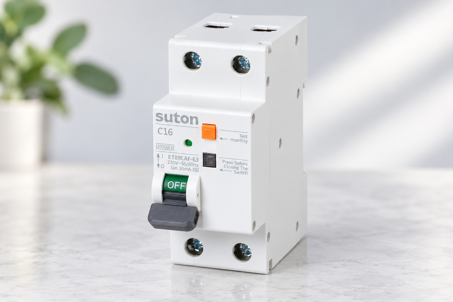
The ETB9LAF-63 product page shows a physical SUTON AFDD family. The ETB9LAF-40 page shows another form factor. The photos help check board space, terminal locations and the test control, but they do not demonstrate compatibility with a particular LED driver or inverter. Request the datasheet, wiring diagram, application notes, test-button instructions and any declared load limitations for the exact offered code.
At quotation stage, send the supplier the load models and counts, source arrangement, circuit diagram, board layout, prospective fault current, cable details and protection objectives. Ask for a written response to each item and an explanation of any conditions. If the offer changes the proposed model or firmware revision, update the compatibility review rather than carrying forward an answer for a different device.
Plan a commissioning sequence with representative loads
Before energization, inspect the installation for correct conductor preparation, torque, neutral routing, barriers, labels and source direction. Use the manufacturer’s AFDD test procedure and record the result. If the device has integrated residual-current protection, verify that function separately by the approved method. Do not create an artificial live arc or defeat protective earth to simulate a fault. HSE electrical-safety guidance reinforces planned work by competent people.
Where it is safe and permitted, observe ordinary operation with the representative load combination: standby, startup, switching, dimming, normal running and shutdown. Record any trip indication, time and load state. A successful run is useful evidence for that installation state, not a universal guarantee that no future load will trip. The AFDD commissioning guide provides a separate record for the product test and as-left state.
For a circuit serving several supplies, create a simple operating matrix. Record the state when one supply starts alone, when several start together, when a motor changes speed, and when a control switches the load rapidly. Note the source mode and any equipment configuration that affects normal operation. This is an observation of permitted use, not a request to stress equipment beyond its instructions. The matrix helps a technician reproduce a reported event later without guessing which combination was present. If a load cannot safely be cycled during commissioning, record that limitation and plan a later observation with the operator.
Diagnose an operation before changing the design
If the device trips, first record the indication and operating state. Identify whether an integrated overcurrent or residual-current function may have operated. Look for damaged cords, loose connections, moisture, overloaded circuits and altered loads. Compare the as-found condition with the installation drawing and product instructions. Avoid repeatedly resetting the circuit or replacing the AFDD without evidence. The AFDD troubleshooting guide gives a structured event log.
A repeated trip tied to one electronic load deserves investigation of that load and its wiring, but the correlation alone does not prove either the load or AFDD is defective. Ask the equipment and AFDD manufacturers for model-specific guidance. If a repair or change is made, repeat the relevant test and document the as-left result. Keep temporary operating limitations visible to maintenance staff.
Preserve the selection basis for future changes
Give each significant electronic load an identifiable entry in the handover list, including its equipment model and the circuit on which it was assessed. For equipment with several normal modes, distinguish the modes actually observed from those that were unavailable during commissioning. This avoids treating a brief standby observation as evidence about operation at full output. When an operator later reports a trip, the maintenance team can compare the connected equipment with that dated baseline. If a power supply has been replaced, record the new model and request any necessary compatibility review before concluding that the original commissioning result still represents the installation.
At handover, retain the exact AFDD code, connected-load list, source-mode drawing, supplier response, installation manual revision, test result, status-indication legend and maintenance instructions. Explain that a later charger, supply, dimmer or motor controller change may require a new review. The circuit-breaker types guide provides the broader protection context, while this article’s approval remains specific to the installed circuit and loads.
Mark unresolved compatibility questions explicitly in the procurement record. A broad promise that “all electronic loads are fine” is not auditable. A list of tested or declared conditions, plus an as-left observation record, gives the next designer a practical starting point when the installation evolves.
Date the review and identify the person responsible for approving each remaining condition.
Educational video
This independent demonstration supports the AFDD principles discussed here. It does not replace SUTON model instructions or an approved installation test.
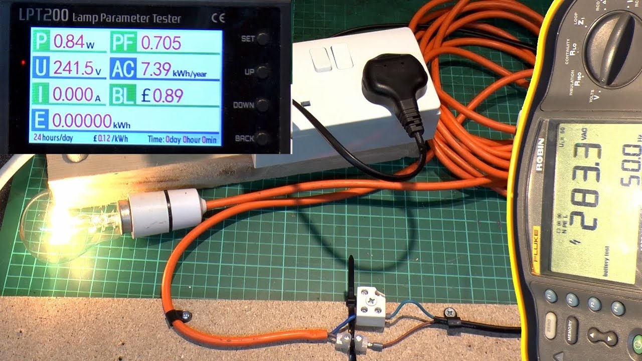
Watch AFDD Arc Fault Detection Devices Additional Tests (Part 2) on YouTube.
Frequently asked questions
Do LED drivers always cause AFDD nuisance trips?
No. Review the actual driver models, circuit, product instructions and event evidence instead of generalizing.
Can an AFDD be used with a variable-speed appliance?
Possibly, subject to the exact equipment and AFDD instructions, circuit study and commissioning observations.
Does an AFDD trip identify an arc fault by itself?
Check the product indication and any integrated overcurrent or residual-current function before assigning the cause.