A side-operated switch disconnector places the operating interface at the side of the switch, while a front-operated arrangement approaches the mechanism from the front. The useful choice depends on the cabinet layout, handle location, shaft or linkage route, conductor space and maintenance access. Neither arrangement is automatically safer, smaller or electrically superior. Compare complete, approved configurations against the actual panel drawing. This guide focuses on mechanical layout and procurement for SUTON HGL(ETGL)/C side-operated and related front-operated arrangements; it does not provide instructions for adapting a mechanism or bypassing an interlock.
Begin with the operator's access position
Mark where the authorized operator must stand and where the handle must be located. Consider the normal operating condition, maintenance access and the surrounding equipment. The most convenient location on an empty drawing may be obstructed by an adjacent cabinet, a wall or a door when the equipment is installed. Record those physical constraints before choosing the switching arrangement.
The handle location and the mechanism location are related but not identical. An external handle can connect to an internally mounted switch through a specified shaft or linkage. Identify both positions and the permitted route between them. Do not select a switch only from the orientation of a catalogue photograph. Ask for the drawing of the exact arrangement proposed for the cabinet.
Distinguish side operation from external operation
Side operation describes the switch mechanism's operating approach. External operation describes a handle accessible from outside the enclosure. A side-operated product can have an external arrangement, and a front-operated product may also have one. These terms should therefore occupy separate fields in the equipment schedule.
The SUTON HGL(ETGL)/C side-operated product page describes direct operation with the handle on the right-hand side and an external operating arrangement using a linkage. It identifies C as side operation and CK as side operation with a viewing window. This is useful configuration information, but the exact offered assembly and accessories still need to be identified. A quotation that simply says “side handle included” does not describe the full enclosure interface.
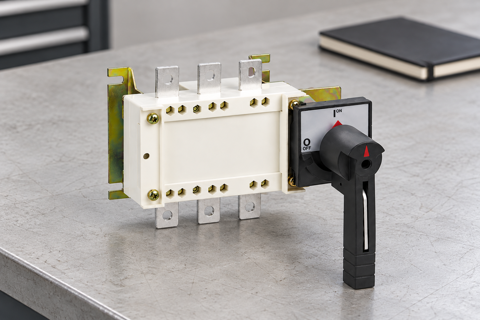
Preserve the electrical-duty limits during layout selection
Mechanical convenience does not resolve voltage, load category, current or fault-duty suitability. The HGL(ETGL)/C page describes three-pole and four-pole versions and states that models at specified larger current ratings are for electrical isolation only. The related HGL(ETGL) load-disconnector page also distinguishes duties within the range. Retain those conditions when comparing orientations.
Do not choose a physically convenient large model and assume that it can switch the required load because a smaller family member can. Ask for the exact applicable operational rating and utilization category. The switch-disconnector making and breaking capacity guide covers the adjacent electrical review. That review must remain open until the mechanical and electrical proposals describe the same product code.
Compare the complete operating envelopes
| Layout item | Side approach review | Front approach review |
|---|---|---|
| Operator access | Side mechanism and external handle positions | Front mechanism and external handle positions |
| Reserved space | Side clearance and neighboring equipment | Cabinet depth and door equipment |
| Linkage | Exact approved components and alignment | Exact approved components and alignment |
| Conductors | Check side route conflicts | Check front and depth conflicts |
| Viewing | Confirm C or CK configuration and sight line | Confirm offered indication and sight line |
| Maintenance | Retain complete permitted access envelope | Retain complete permitted access envelope |
| Electrical duty | Verify the exact model independently | Verify the exact model independently |
The comparison should use the full outline and operating drawings rather than only the closed switch dimensions. A front approach can be constrained by cabinet depth or a door-mounted device. A side approach can be constrained by side-wall clearance or neighboring equipment. The supplier should identify the required space for the specified mechanism, including any movement or access needed under the approved arrangement.
Where two proposals both fit, compare installation and maintenance consequences rather than inventing a universal preference. The better arrangement is the one that satisfies the documented requirements with a clear accessory list and an achievable inspection method. Retain the accepted envelope on the final panel drawing so later additions do not occupy reserved space.
Review shaft and linkage compatibility before ordering
An external operating mechanism is a system of matched components. Ask for the approved handle, shaft or linkage, supports, coupling and mounting details for the selected switch. A similar-looking shaft from another frame is not automatically compatible. Its length, engagement and permitted alignment must follow the actual instructions.
Avoid treating field cutting, bending or repositioning as a routine way to make an unsuitable mechanism fit. Where adjustment is permitted, the manufacturer's method and limits govern it. If the proposed enclosure depth or handle position falls outside the approved arrangement, obtain an engineered alternative before procurement. A supplier response should state the supported configuration rather than leaving the installer to improvise it.
Keep door interlocks as a separate requirement
The presence of an external handle does not establish every required door-interlock function. Identify which door or cover is controlled, what operation is restricted and how any authorized access provision is managed. Ask for the exact mechanism and accessory evidence. Do not assume that a standard handle includes a function described elsewhere in a family brochure.
The door-coupled rotary handle interlock guide explains that specific interface. This article addresses the broader orientation and layout choice. Keep the scopes separate: selecting a side-operated arrangement does not, by itself, approve a door interlock, and a door interlock does not resolve cable clearance or mechanism access.
Check conductor routing and terminal access
Place the actual terminal arrangement and conductor routes on the layout. Consider cable bending space, lug access, terminal barriers, torque-tool access and the distance from moving mechanism parts. An operating linkage must not become an unplanned obstruction to a conductor route or maintenance approach. Use the approved conductor and terminal instructions for the selected configuration.
A front-operated proposal may leave one region clear while consuming cabinet depth elsewhere. A side-operated proposal may improve one cable path while obstructing another. Compare those effects using the real panel dimensions. Do not estimate terminal locations from a photograph or assume that changing orientation preserves every cable-entry option. Request a drawing that shows the delivered arrangement and mounting points.
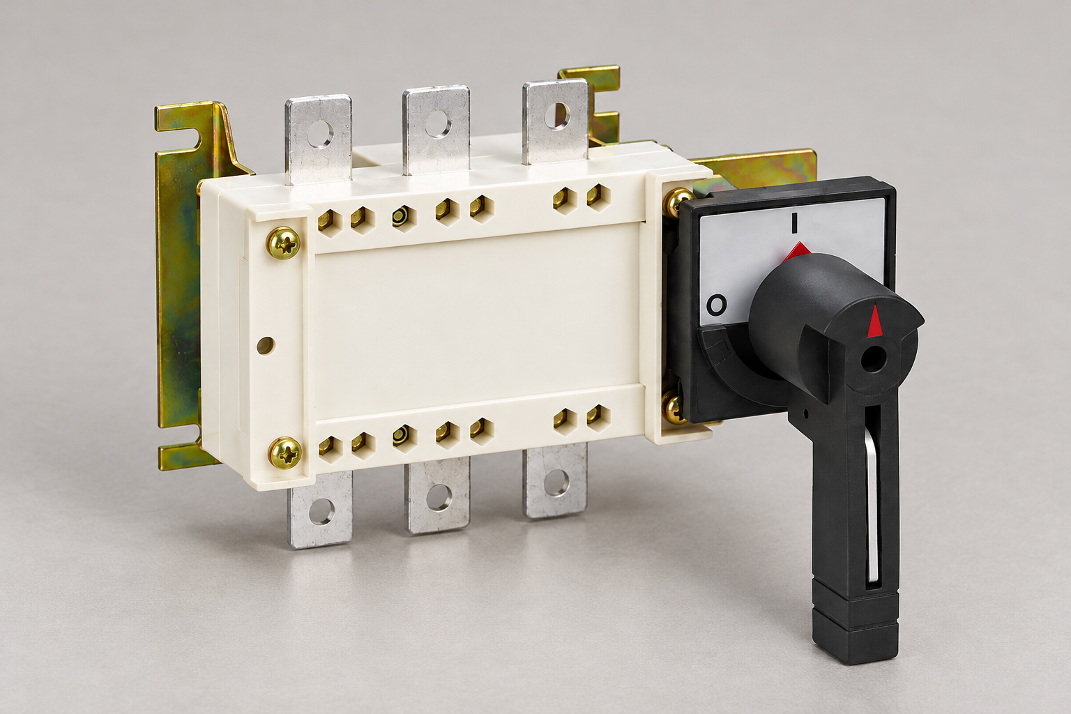
Plan the viewing and indication requirements
The C and CK distinction on the product page makes the viewing feature an explicit purchasing question. If a contact-viewing window is required, identify the configuration and the installed sight line. A window hidden behind a barrier or cabinet flange may not satisfy the intended inspection requirement. Record what can actually be observed from the approved access position.
Distinguish direct observation from a mechanical position indicator or an auxiliary signal. Each can provide useful information, but each represents a defined function. None establishes the electrical condition of every conductor by itself. The HSE guidance on work near electricity supports keeping suitable isolation and reliable verification distinct from the appearance of a switch handle or indicator.
Inspect the delivered mechanism against its approved arrangement
At receipt, compare the switch identity, pole count, operating side, handle, linkage and accessories with the approved order. Check for transport damage and retain the exact instructions. Before energization, the approved acceptance plan should confirm the intended movement, indication and any specified interlock functions under safe conditions. This article intentionally provides no generic operating force, shaft engagement dimension or live test sequence.
Record discrepancies before the equipment is released. A handle that reaches its marking while the mechanism has not achieved the required state is not a cosmetic issue. Unexpected resistance, lost motion or disagreement between local and remote indications needs investigation using the approved documentation. Do not use extra force or modify a stop to make the indication appear correct.
Preserve service access after the cabinet is populated
Recheck the arrangement after wiring ducts, cable terminations, labels and neighboring equipment are installed. Items added late in assembly can obstruct a previously acceptable mechanism or sight line. Include these checks in the final layout review rather than relying on an inspection of the bare mounting plate.
HSE's guidance on working on electrical equipment emphasizes planned work and secure control of energy sources. In this context, maintainability means that the approved inspection and isolation arrangements can actually be used. A compact layout that prevents safe access is not a successful mechanical integration. Where the arrangement changes, obtain the required review before the equipment returns to service.
The isolator switch planning guide provides the parent framework for the equipment role and isolation boundary. Use it alongside this mechanical-layout review so that the chosen arrangement serves a clearly defined circuit function.
Write a layout-led switch inquiry
Send SUTON the single-line diagram, electrical duty, pole arrangement, enclosure depth, mounting plate position, preferred handle location, cable routes and access constraints. State side operation and external operation separately. Identify any viewing window, auxiliary contacts, door interlock or locking provision that the project requires, and request confirmation for the exact order code.
Ask for outline, mounting, operating and accessory drawings together. Compare quotations against that controlled package, and require exceptions to be stated individually. During handover, retain photographs of the final permitted inspection view and link them to the drawing revision. This makes later replacement or expansion easier to review without assuming that every member of the same family shares an identical mechanical arrangement.
Frequently asked questions
Is side operation the same as an external cabinet handle?
No. Side operation describes the mechanism approach; external operation describes where the handle is accessible. Specify both and verify the complete approved arrangement.
Can a shaft from a similar switch be used if it fits?
Do not assume compatibility from appearance or fit. Use the approved components, dimensions and installation method for the exact switch and enclosure arrangement.
Does choosing a side-operated model change its load-switching duty?
Orientation alone does not establish electrical duty. Verify the exact configuration's operational ratings and limitations, including any isolation-only condition stated for the selected model.
Educational video
SELECT Safe Isolation Animation 2024 by SELECT. SELECT is the Scottish electrical trade association. This neutral training animation supports the safe-isolation discussion; it does not establish a SUTON-specific operating sequence or replace the approved site procedure.