


An isolator switch is a panel-level isolation decision — not a catalogue keyword. It defines where the controlled isolation point sits, which protective functions stay separate, how poles and handles fit the layout, and what lockout evidence commissioning will audit later. Device selection implements the plan; skipping the plan produces a board that looks isolated but cannot be locked out, labeled, or serviced with confidence.
Start with the approved single-line diagram and circuit schedule. Name each boundary that requires a defined isolation function, decide poles and operating access, and only then map device families to roles. A generic “isolator switch” label cannot answer those panel questions without the layout and procedure context.
Important: This guide plans isolator switch selection for low-voltage distribution panels in line with assembly integration practice in IEC 61439-1. It cannot approve a specific device marking, visible-break claim, or load-breaking duty where circuit layout, operating procedure, or applicable rules are absent — hold those inputs for engineering review before procurement.
Part 1. Set the isolation point before choosing the device
Ask “where must work stop?” and you are asking a location and procedure question, not a product question. An isolator switch is selected for a documented equipment boundary — a machine section, outgoing feeder, sub-board incomer, or another defined maintenance point — that the approved procedure must make safe.
| Isolation boundary | Typical panel role | Send with quote |
|---|---|---|
| Machine section | Local maintenance isolator | Single-line position and load ID |
| Outgoing feeder | Distribution isolation point | Rated current, poles, and upstream reference |
| Sub-board incomer | Sub-panel isolation boundary | Feeder identity and protective arrangement |
| Defined maintenance point | Lockout/tagout boundary | Operating procedure and access method |
Record the chosen boundary on the single-line diagram before any purchasing conversation starts. Projects that skip this step buy devices twice: once from a catalogue, and again after an inspection finding or unclear lockout arrangement forces a redesign.
Part 2. Separate isolation from protection and main-switch duty
An isolator switch establishes a controlled isolation function when selected and installed for that role. MCB, RCBO, RCCB, and main incomer devices have separate defined roles. Place each requirement in a clear function matrix instead of treating every handle-operated module as interchangeable.
| Panel function | Primary role | Planning consequence |
|---|---|---|
| Isolator / switch-disconnector | Defined isolation at a documented boundary | Requires poles, handle access, and lockout arrangement |
| MCB / MCCB | Overcurrent and short-circuit protection | Does not establish isolation duty by itself |
| Main incomer switch | Whole-board incoming switching | Separate scope — see the main switch selection guide |
| RCCB / RCBO | Residual-current protection | Separate sensitivity and neutral routing rules |
This matrix avoids a layout that looks complete but has unclear circuit responsibility or maintenance ownership. Device-level switch and load-break explanation lives in the circuit breaker switch guide; this article owns isolation-point planning, layout checks, and RFQ inputs only.
Where both isolation and overcurrent protection apply at one location, record the order of protective elements and the authorized operating sequence. Commissioning must be able to prove which function was exercised and which circuit was affected without disassembly.
Part 3. Plan poles, handles, and panel space together
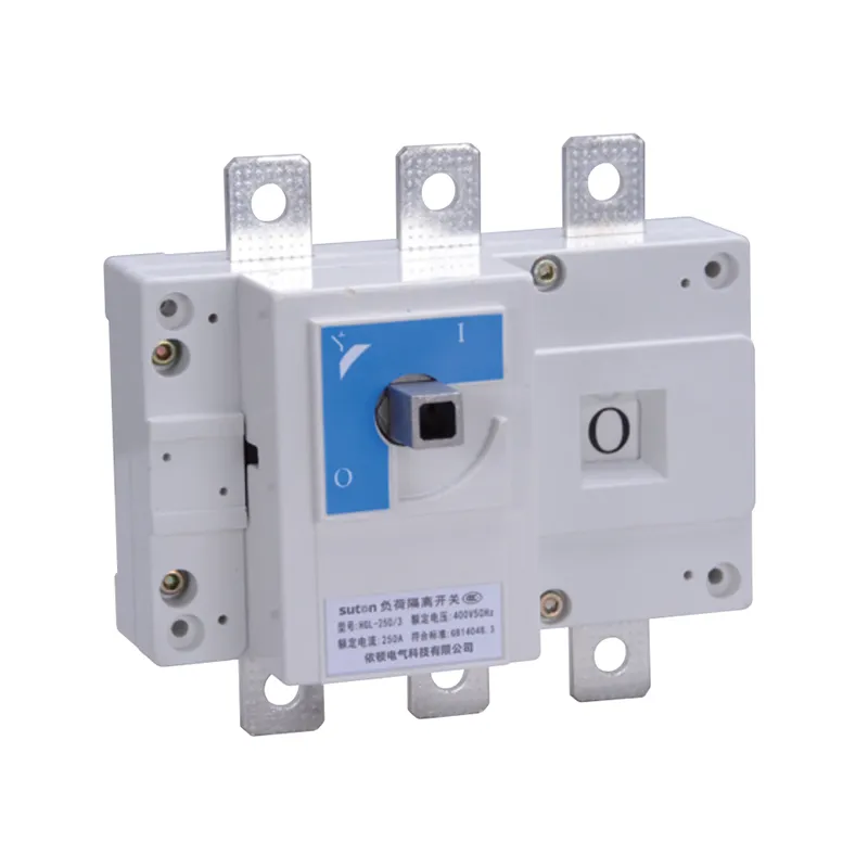
Confirm the phase and neutral arrangement, required poles, handle position, door coupling, labeling space, and working access before freezing the layout. A device that fits on a rail may still fail the service-access, mechanical-interlock, or visible-indication requirement for the documented isolation duty.
Show the isolation point on the assembly drawing and preserve clearance for conductors, terminals, and operating motion. Check physical interfaces early: module width, terminal orientation, bending space, and door clearance for the handle and lockout hasp. A module that fits electrically but cannot be operated or locked out during maintenance becomes a latent compliance gap.
Part 4. Define the operating and lockout workflow
The procedure should identify who operates the device, how the isolated condition is indicated, and how unauthorized re-energization is prevented. Coordinate labels, lockout points, enclosure access, and the applicable maintenance procedure with the approved project documentation.
Do not invent a visible-break, load-breaking, or fault-clearing claim unless the exact configuration and project evidence establish it. Write the authorized operating sequence into the plan on day one. Typical records include circuit identity, device marking, date, operator, and the isolation state achieved.
If an unauthorized energization risk is identified during review, record connected loads, switching context, and enclosure access before changing the arrangement — patterns across records distinguish a procedure gap from a layout issue that the strategy did not anticipate.
Part 5. Review interfaces before releasing procurement
Before any quotation is compared, reconcile the isolation boundary, protective arrangement, conductor interfaces, enclosure conditions, and operating method against the approved drawing. A shared comparison table makes missing evidence visible before assembly begins.
| Interface check | Why it matters |
|---|---|
| Single-line position and circuit identity | fixes where isolation is expected |
| Phase, neutral, and pole count | validates switching category |
| Handle, door, and lockout access | validates serviceability |
| Upstream overcurrent protection reference | separates isolation from protection duty |
| Enclosure temperature and grouping | affects operating conditions |
| Standards requested and quantity | fixes approval and assembly scope |
Require suppliers to declare the exact offered marking, installation instructions, accessories, and exceptions. Hold the engineering decision when the required isolation boundary or circuit information is incomplete — a quotation against an undefined single-line position cannot preserve the design intent.
Part 6. Route an evidence-based SUTON inquiry
Send with the inquiry:
| RFQ input | Why it matters |
|---|---|
| Single-line diagram with isolation points marked | shows where isolation is required |
| Circuit schedule with load and boundary notes | validates poles and duty |
| Required protective functions per location | separates isolation from overcurrent and residual roles |
| Rated current, poles, voltage, and mounting interface | fixes physical and electrical duty |
| Operating method, lockout arrangement, and labeling requirements | fixes maintenance scope |
| Standards requested, accessories, and quantities | fixes approval and assembly scope |
SUTON’s modular DIN rail products category is a public route for discussing modular switching families after the buyer has defined the required function and project conditions.
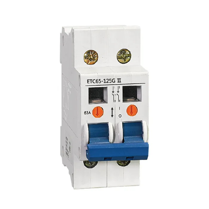
Where the approved design calls for a DIN-rail isolation function, the public DZ47-125G miniature switch-disconnector route may support an inquiry once the isolation boundary is documented. For feeder-level load-break or switch-disconnector duties, review the ETGLHGL series load-break switch-disconnector route against the same controlled drawing.
These public pages do not fix marking, switching category, coordination, or installation exceptions for a specific panel — those remain project-specific confirmations. Send the controlled schedule and drawing references through Contact SUTON for model-level review.
Fit Boundary: this guide structures isolator switch planning for LV distribution panels. It does not decide national rule applicability, does not replace a coordination study, and cannot approve a device where the isolation boundary, operating procedure, or rule references are missing. Escalate those gaps to the design authority before the plan is priced.
Product recommendation boundary
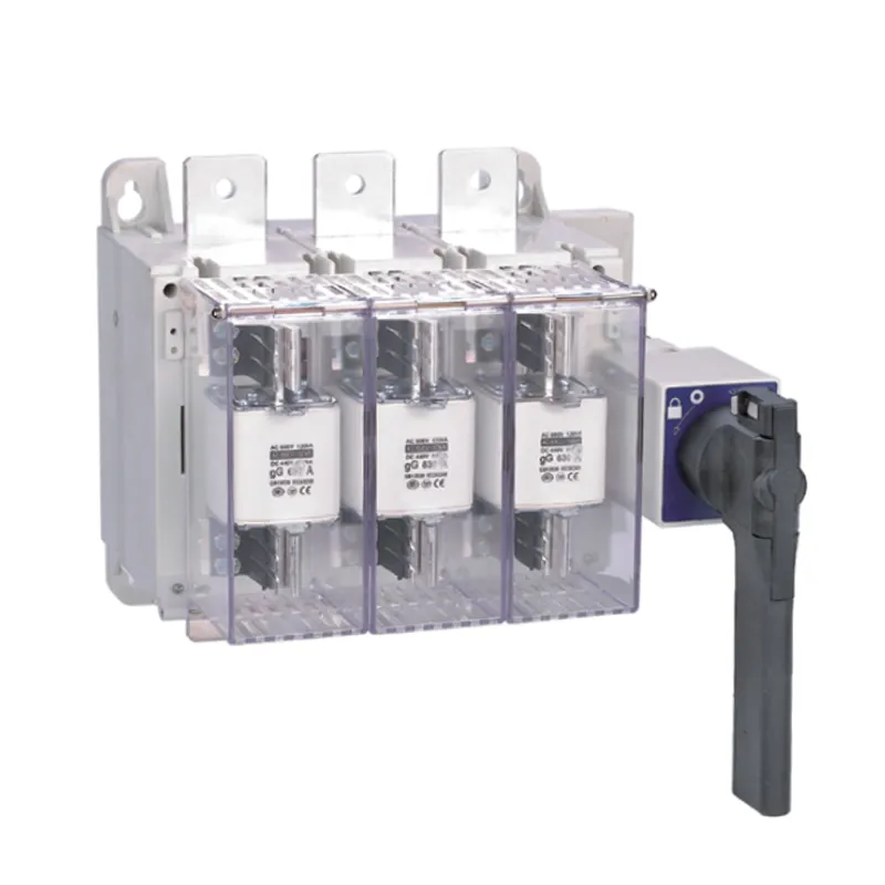
Once the isolation matrix and single-line diagram are approved, use SUTON product routes as inquiry context — not as proof of project suitability.
The modular DIN rail products category covers modular switching families. The DZ47-125G miniature switch-disconnector and ETGLHGL series load-break switch-disconnector routes support feeder and branch isolation discussions where the schedule documents that duty.
For whole-board incomer scope, cross-read the live main switch selection guide before mixing incomer and local isolation devices in one schedule. Hold every supplier quotation to the same isolation schedule and archive the approved version with the panel dossier.
Panel dossier and service discipline
Treat the isolation-point map, circuit schedule, lockout procedure, test records, and revision history as one handover package. Facilities that inherit the strategy maintain it; facilities that inherit only a rail full of handles tend to rebuild the plan from scratch at the first service event.
After any unexplained access or energization issue, record the circuit, connected loads, lockout state, and recent switching activity before reset. Compare the event against the approved boundary: a missing label, an inaccessible handle, or a procedure mismatch often explains the symptom faster than replacing the device by default.
When circuits are added or rearranged, revise the isolation-point map and device schedule before re-energizing. A new branch can change lockout access and pole duty even when the catalogue rating looks unchanged.
FAQ
What is an isolator switch used for in a panel?
It defines a controlled isolation point for a documented equipment boundary and maintenance procedure.
Is an isolator switch the same as a main switch?
No. This guide covers local isolation planning; the main switch selection guide covers whole-board incomer selection.
Does an isolator switch provide overcurrent protection?
No. Keep overcurrent protection as a separately specified function in the device schedule.
How many poles should an isolator switch have?
Match the documented phase and neutral isolation requirement and the approved panel drawing.
What should an isolator switch RFQ include?
Include the isolation boundary, poles, panel location, interfaces, operating and lockout method, enclosure conditions, standards requested, and quantities.
Can a catalogue page prove project suitability?
No. Verify the exact offered configuration against the controlled project requirement before release.