


MCB breaking capacity selection should be decided from the complete circuit duty, not from one label on the breaker. MCB breaking capacity must be verified against the prospective short-circuit current at the exact installation point and at the actual system voltage. The ampere rating describes normal current duty; it does not show whether the breaker can safely interrupt the available fault. For panel builders and technical buyers, the safe result is a documented match between the load, conductors, available fault current, protective-device behavior, installation environment and applicable project rules. This guide provides a practical selection and review workflow. It does not replace the project protection study, local electrical requirements or the exact instructions for the offered device.
Quick answer
MCB breaking capacity must be verified against the prospective short-circuit current at the exact installation point and at the actual system voltage. The ampere rating describes normal current duty; it does not show whether the breaker can safely interrupt the available fault. Use a current short-circuit study and exact manufacturer ratings. Apply backup or cascading claims only when valid combination evidence exists. The final choice must be traceable to the exact product variant and the actual installation.
| Decision input | What to verify | Evidence to keep |
|---|---|---|
| System duty | Voltage, frequency, AC/DC arrangement and earthing | Approved single-line diagram and equipment schedule |
| Normal load | Continuous current, duty cycle, simultaneous loads and inrush | Load data, measurements and design calculation |
| Fault duty | Maximum and minimum prospective fault current | Current short-circuit and protection study |
| Protective behavior | Use a current short-circuit study and exact manufacturer ratings. Apply backup or cascading claims only when valid combination evidence exists. | Exact manufacturer curve, settings and application table |
| Installation | Ambient temperature, grouping, enclosure, terminals and conductors | Panel layout, instructions and inspection record |
| Coordination | Upstream and downstream device behavior | Selectivity or backup evidence for exact devices |
Standards and safety references: IEC 60898-1, IEC 60947-2, OSHA 1910.303 and OSHA 1910.333. Use the edition and local adoption required by the project.
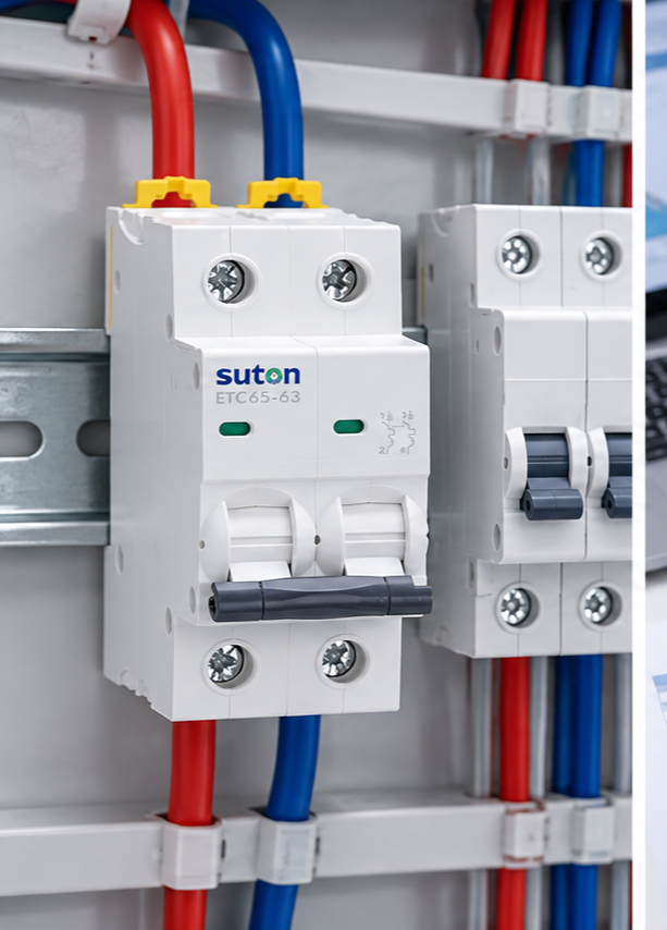
Define the circuit duty before choosing the breaker
Begin with the source and load, not the breaker catalog. Record nominal and maximum system voltage, frequency, phase arrangement, earthing system, normal current, duty cycle and the way the load starts or switches. Identify motors, transformers, LED drivers, power supplies, capacitors and other equipment that can create a short current peak. A low steady-state current does not guarantee a low inrush, and a large inrush does not by itself justify a slower protective characteristic.
Next record conductor material, cross-section, insulation temperature, installation method, grouping, ambient temperature and route length. The breaker must protect the conductor under the adopted design rules. If a proposed change reduces unwanted trips but allows the conductor to remain exposed to damaging current for too long, it is not a valid solution.
Separate overload, starting current and short-circuit behavior
Overload protection deals with current above normal load that persists long enough to heat conductors and equipment. Starting or inrush current is usually brief and expected. Short-circuit protection addresses a much higher fault current that must be interrupted within the device rating and the required time. These regions overlap on a time-current graph, so the review must use both current and time.
Plot or compare the expected load envelope with the breaker tolerance band. The load should remain to the non-operating side during acceptable operation, while damaging overload and the minimum credible fault must fall within the required operating region. Use the complete tolerance band rather than a single ideal line. Verify that the available fault current does not exceed the device’s declared breaking capacity at the installed voltage.
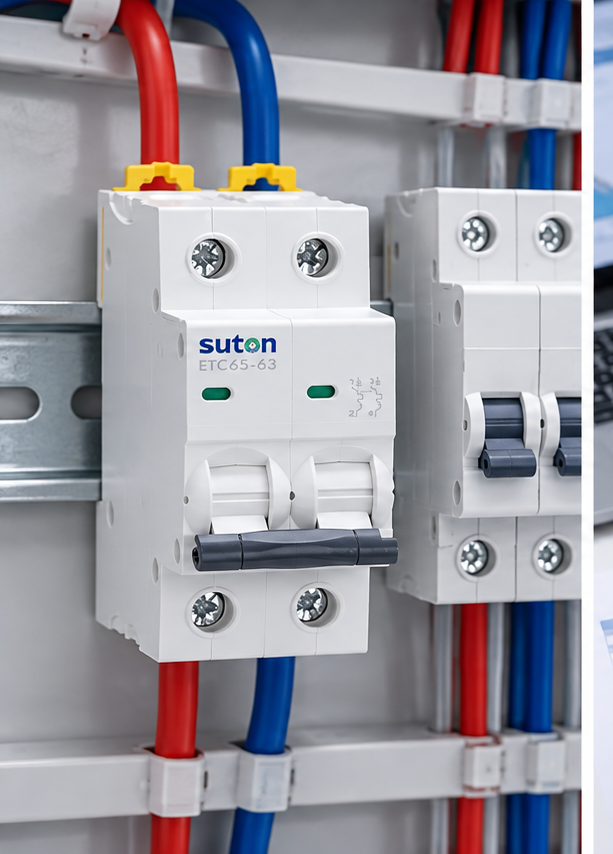
Read the exact manufacturer information
Family names and front labels are not a complete specification. Obtain the datasheet and instructions for the exact catalog number, poles, trip unit and accessories. Check rated operational voltage, rated current, frequency, utilization conditions, breaking capacity, reference ambient temperature, conductor range, terminal torque, mounting orientation and environmental limits. For adjustable equipment, record the sensor or rating plug and every active setting.
Use a current short-circuit study and exact manufacturer ratings. Apply backup or cascading claims only when valid combination evidence exists. When the product data does not cover the intended duty, ask the manufacturer for a written application statement or select a device with declared suitability. Do not create a rating by combining unrelated values from several brochures.
Check maximum and minimum fault current
The maximum prospective fault current tests whether the breaker can interrupt the fault safely. The minimum fault current tests whether the selected protective characteristic will operate quickly enough at the remote end of the circuit. Both matter. A choice that survives the maximum fault but cannot clear a lower remote fault within the required time remains unsuitable.
Use a current short-circuit study that reflects transformer data, source configuration, cable impedance, parallel paths and operating modes. Standby generators, photovoltaic systems, UPS equipment and alternative bus configurations can change the result. Record the study revision used for the final selection.
Coordinate upstream and downstream protection
Compare the proposed device with upstream and downstream breakers, fuses and protective relays. Decide where selective operation is required and over what fault-current range. Two devices with different current ratings can still operate together if their instantaneous regions overlap. Conversely, a tested manufacturer combination may provide backup protection beyond the downstream device’s standalone rating.
Use exact curves and manufacturer selectivity or cascading tables. Confirm voltage, device variants and settings match the published combination. State whether the result is full selectivity, partial selectivity to a declared current, or backup protection. These are different claims and should not be used interchangeably.

Account for the panel environment
The air around the breaker may be warmer than the room. Heat from neighboring devices, restricted ventilation, enclosure solar gain and continuous loading can raise the local temperature. Altitude can affect cooling and dielectric performance. Use manufacturer correction data for the exact product and assess the complete assembly rather than applying an unverified universal factor.
Check clearances, mounting, conductor bending space and access for inspection. Terminals must accept the planned conductor type, number and cross-section. Use the declared preparation method and tightening torque with a controlled tool. A breaker can be electrically suitable but still be a poor panel choice if the terminal or installation arrangement cannot be executed reliably.
Common selection mistakes
- Choosing from normal load current while ignoring inrush and duty cycle.
- Increasing the current rating or slowing the curve only to stop tripping.
- Confusing continuous-current rating with breaking capacity.
- Assuming an AC rating automatically applies to DC or another frequency.
- Using a generic curve instead of the exact model tolerance band.
- Ignoring minimum fault current and required disconnection time.
- Claiming selectivity or cascading without exact combination evidence.
- Copying settings, torque or derating values from a similar-looking product.
Commissioning and verification
Before energization, verify device identity, poles, markings, settings, accessories, conductor placement, terminal work, barriers and labels. Compare the installed configuration with the approved schedule and study. For adjustable trip units, use the test method required by the project and manufacturer. Record as-left settings so a later inspection can detect unauthorized changes.
Electrical work can expose people to shock and arc-flash hazards. Establish an electrically safe work condition whenever required. Identify all sources, isolate them, apply the approved lockout procedure and verify absence of voltage with suitable equipment. Energized measurements may be performed only by qualified people under the site risk-control process.
Information to include in an RFQ
Send the supplier the system voltage and frequency, AC or DC duty, poles and neutral arrangement, continuous load, starting or inrush data, maximum and minimum fault current, required breaking capacity, conductor details, enclosure temperature, altitude, coordination objective, accessories and documentation requirements. Ask for exact datasheets, curves, dimensions, wiring diagrams and combination tables.
For a matching product discussion, review the relevant SUTON breaker product page. Use the circuit breaker types guide as the parent overview, and compare the separate guides on breaking capacity, selectivity and commissioning.
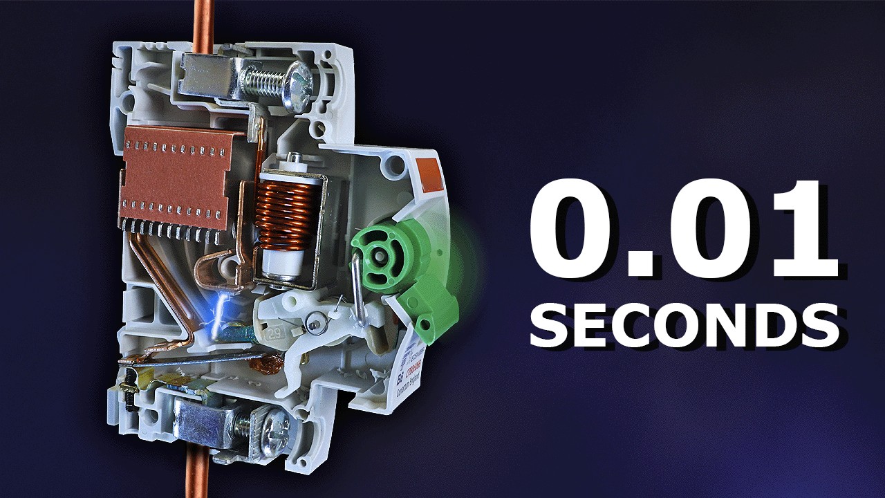
Educational video: circuit breaker fundamentals
This neutral engineering explainer supports the operating-principle discussion. It does not replace project calculations or manufacturer instructions.
Frequently asked questions
Can MCB breaking capacity selection be decided from the ampere rating alone?
No. Voltage, fault duty, time-current behavior, conductor protection, installation conditions and coordination also affect the decision.
What information should be requested from the breaker supplier?
Request the exact catalog number, applicable standard, declared ratings, time-current curves, terminal data, environmental limits, accessory diagrams and coordination evidence.
Should an existing breaker setting or curve be copied to a new panel?
No. Confirm the present system study, load, conductors, source capacity and project rules. Similar panels can have different fault levels and operating objectives.
Final review checklist
Confirm the exact circuit duty, conductor protection, load envelope, maximum and minimum fault current, breaker curve or settings, breaking capacity, coordination evidence, environmental corrections, terminal arrangement and commissioning record. Resolve every missing input before approving the device. A defensible selection is one another engineer can reproduce from the saved drawings, calculations and exact manufacturer documents.