A switch disconnector door interlock links the external operating handle and enclosure door so that access follows the intended switching position. A complete selection must match the switch, handle, shaft, enclosure geometry and documented interlock functions. A rotary handle alone does not prove that an interlock exists, and an OFF indication does not prove that every exposed conductor is dead. For panel builders, the useful question is therefore not simply whether a handle fits. It is whether the assembled mechanism provides the specified access control and isolation function throughout its supported installation and maintenance conditions.
Identify the mechanism you are buying
Door-coupled operation usually places the external handle on the door and the switch inside the enclosure. An extension shaft transfers the operator's movement to the switch mechanism. Opening the door changes that mechanical relationship, which is why compatibility includes shaft engagement, door position and the behavior of the handle when disconnected. A drawing of the switch body cannot answer all of these questions.
Specify the arrangement before requesting a quotation: direct operation, extended door operation, or an alternative supported assembly. Record the manufacturer's switch code, frame, handle code, shaft code and any additional interlock components. Two handles with similar colors may support different mechanisms. Treat substitutions as engineering changes requiring evidence, rather than interchangeable cosmetic parts.
The IEC 60947-3 product scope includes switches, disconnectors, switch-disconnectors, fuse-combination units and dedicated accessories. The relevant declaration and instructions must identify the actual assembly. This article provides a procurement review framework; it does not establish compliance or an accessory combination for a particular panel.
Separate door locking from OFF-position locking
A door interlock and a padlocking facility solve different problems. Door interlocking controls access according to the declared operating condition. OFF-position locking restricts operation of the disconnecting means. A design can provide one function without the other, or provide both with different conditions. Record each required behavior separately in the purchase specification.
Ask whether the door is prevented from opening in ON, whether closing is required before the device can be switched ON, and which positions permit removal or disengagement of the handle. Ask how the assembly behaves with the door open and what indication is available at the switch itself. Answers should reference instructions or a functional drawing, not a generic promise that the handle is safe.
Where a controlled override exists, obtain its intended use and restrictions. This is not an invitation to bypass a mechanism. HSE maintenance guidance emphasizes isolation and preventing unintended restart before maintenance. Interlocks alone do not establish that equipment is safe to access. Local rules and a competent person's procedure govern actual access.
Check the enclosure geometry before ordering
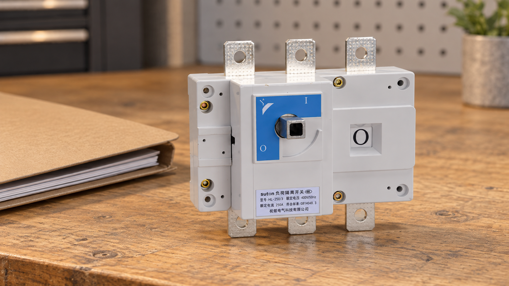
The door thickness, shaft centerline, mounting depth, hinge position and internal clearances form one mechanical system. A handle selected by switch current alone can fail because the shaft is too short, its alignment is wrong, or another component obstructs the coupling. Include a dimensioned enclosure drawing in the enquiry and identify the precise reference surfaces used for measurement.
Do not cut a shaft from an estimated photograph. The manufacturer's accepted length range and cutting instructions control. Changes to hinges, mounting plates or gasket compression can alter engagement even when the nominal enclosure dimensions stay the same. Record the final assembled geometry and review whether tolerances permit reliable operation throughout the expected door movement.
Cable bending space also matters. A mechanically compatible handle does not make an overcrowded enclosure acceptable. Consider access to terminals, protective covers, adjacent devices and the required working space independently. For the electrical selection that accompanies the mechanical review, use the switch-disconnector making and breaking capacity guide rather than inferring duty from the handle.
Use a function-based acceptance table
| Required function | Information to request | Acceptance basis |
|---|---|---|
| Door access in ON | Exact supported interlock behavior | Selected mechanism instructions |
| OFF locking | Padlock provisions and limits | Approved energy-control arrangement |
| Mechanical interface | Switch, handle and shaft codes | Supported assembly drawing |
| Enclosure fit | Door thickness, depth and alignment | Accepted geometry and tolerances |
| Indication | Handle-to-switch relationship | Documented inspection procedure |
| Replacement | Controlled spare/accessory codes | Approved repeatable combination |
This table is a qualitative enquiry checklist, not a dimensional specification or an instruction to operate energized equipment. Populate its evidence column with the selected manufacturer's documents and the panel builder's approved assembly information. Unanswered conditions remain open until the responsible reviewer accepts them; a visually similar accessory is not a substitute for that review.
For example, a proposed door operator may fit the mounting holes but lack documented operation with the specified switch frame. Another proposal may have the correct switch interface but require a different door cutout. Compare the complete combinations. The cheaper handle is not necessarily the cheaper assembly once redesign, replacement and inspection are included.
Review indication and abnormal conditions
External handle position is an indication whose reliability depends on the supported mechanism and installation. Ask how the operator position relates to switch position, how incomplete engagement is prevented or detected, and which observations are required during commissioning. A stiff handle or an unusual stop position should be investigated under the manufacturer's procedure, not corrected by applying more force.
Specify who will inspect the system after door, shaft or switch replacement. An interlock that originally worked can become unreliable after an unapproved accessory substitution or enclosure modification. Keep a record of accepted part numbers and assembly drawings so that maintenance staff do not need to reconstruct the combination from appearance.
The electrical isolation boundary is separate from the mechanical door boundary. Incoming terminals, another supply, auxiliary power or stored energy can remain hazardous even when the main switch is OFF. The HSE guidance on secure isolation provides general principles; the equipment-specific procedure must identify the relevant sources and verification points.
Define commissioning evidence without improvised tests
Ask the panel builder to produce an inspection record under an approved commissioning procedure. Its scope should include accessory identity, fastener and mounting requirements, shaft preparation, alignment, enclosure sealing and the declared interlock functions. Testing conditions, equipment state and responsible personnel must be defined before the review begins.
This is not a live-work test recipe. Functional checks must follow manufacturer instructions and the site's safety arrangements. Do not request an operator to demonstrate access to energized parts, defeat an interlock or prove contact isolation by opening the door. Documented acceptance criteria allow the builder to demonstrate the supported functions without turning a buying checklist into unsafe instructions.
Keep the result linked to the assembly serial number or project reference. Record exceptions and their resolution. If the drawing changes after acceptance, determine which checks need to be repeated. A signed record is most useful when it identifies the actual combination and conditions, rather than simply stating that a rotary handle was inspected.
Keep switching duty and pole selection in the review
Mechanical suitability does not establish load-switching suitability. Obtain operational ratings at the actual voltage and supported utilization category, short-circuit coordination, conductor requirements and environmental limits. A door-coupled mechanism should not change the evidence required for the switch itself. Check any restrictions associated with the particular accessory arrangement.
Use the three-pole versus four-pole selection guide to review conductor functions separately from handle geometry. Neutral treatment and additional sources cannot be settled by the number of handle positions. Where motor switching is involved, review the motor duty, control arrangement and exact accepted operational rating.
A purchase specification should state whether the device is intended for maintenance isolation, routine load switching, or another supported role. These roles influence the required documents, expected operating frequency and lifecycle plan. Do not let a convenient door layout obscure the fundamental circuit requirements or substitute a mechanism rating for the power device's electrical declaration.
Request a supported SUTON accessory combination
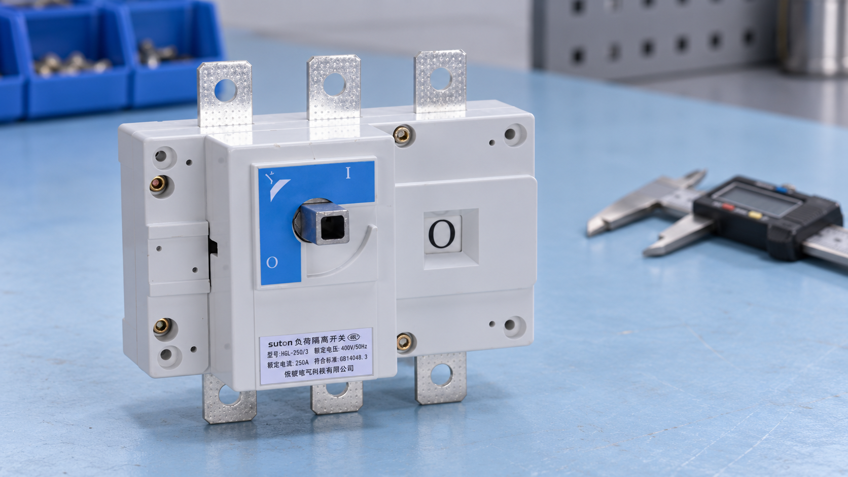
The SUTON ETGL(HGL) load-break switch-disconnector is a relevant starting point for a switch enquiry. The product exterior shown here identifies the reference family; it does not prove availability of a particular door-coupled handle, shaft or interlock. Request confirmation for the exact switch code and enclosure arrangement before releasing the bill of materials.
Send the intended electrical duty, conductor diagram, enclosure drawing, operating-side preference, door thickness and access-control requirements. Ask SUTON to identify the supported accessory codes and provide installation instructions. Include whether OFF padlocking is required and how replacement accessories will be controlled during maintenance. Do not specify an improvised adapter based on a photograph.
Prepare the enquiry as one package rather than separate orders for a switch and a handle. A coordinated response makes it easier to identify missing interfaces and allocate responsibility for the final assembly. Contact SUTON with the project documents and ask for a complete supported proposal, including any limitations that affect installation or acceptance.
For the overall equipment review, use the disconnect-switch guide for panel builders as the parent selection framework. Apply this article to its specific door mechanism evidence requirements.
Frequently asked questions
Does a door interlock replace lockout and verification?
No. Door access control is only one part of an equipment arrangement. Electrical work requires the applicable isolation, energy-control and verification procedure. A locked door or an OFF handle indication alone does not establish that every part a person may contact is deenergized.
Can any rotary handle be fitted to the same switch?
No. Compatibility depends on the exact switch mechanism, accessory interface, shaft, enclosure and documented functions. Matching color, nominal current or mounting-hole appearance is insufficient. Obtain supported part codes and instructions, and preserve them with the final assembly record.
What should a retrofit enquiry include?
Provide the existing switch and accessory identifiers, clear exterior photographs, enclosure dimensions, shaft geometry, electrical duty and required door behavior. Report the observed problem without operating damaged equipment. The responsible supplier and panel reviewer should decide whether replacement, redesign or a supported new combination is required.
Educational video
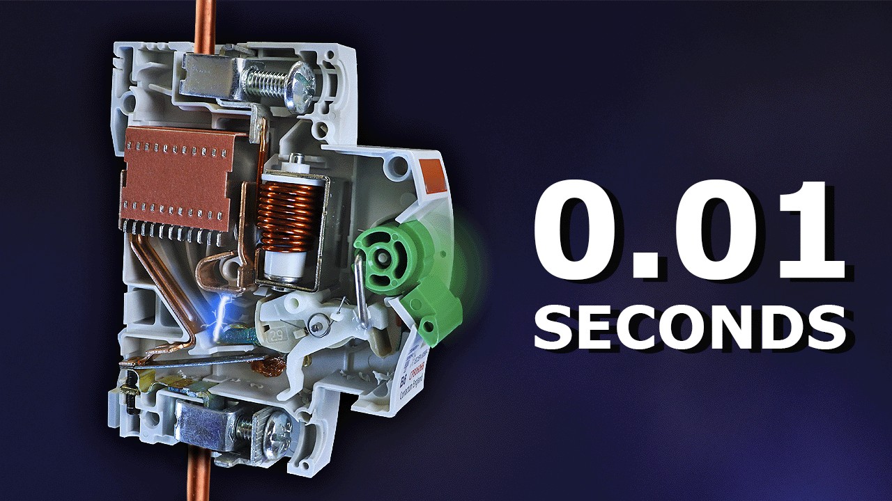
Why Circuit Breakers DON'T Protect People (electric shocks) by The Engineering Mindset. This video explains electrical-shock protection limits; it supports the safety-function distinction here, not an exact SUTON rating, PV connection, fuse selection or installation procedure.