


Thermal overload is a motor-duty question — not a setting knob. It describes the current-time heating condition that the protective arrangement must recognize without treating a normal start as a fault. Begin with the motor nameplate, documented running load, starting profile, and panel-side thermal conditions; only then review trip class, device role, or procurement options.
Important: This guide structures thermal-overload duty evidence and repeat-trip diagnosis for motor feeders in line with assembly integration practice in IEC 61439-1. It cannot approve a setting change, select an overload relay, or release a component route where motor data, trip-class basis, or coordination evidence is missing — hold those inputs for engineering review before pricing.
Part 1. Turn thermal overload into a motor-duty review
Ask “what is the thermal overload setting?” before the motor schedule is complete, and the question collapses into a guess. Thermal overload describes the heating duty the protection must coordinate with: rated current, start duration, cyclic loading, ambient temperature, and the driven-machine behaviour. The phrase is a review boundary, not a substitute for naming the protective element, its setting basis, or the authorized coordination study.
Projects that treat thermal overload as a label on a datasheet skip the evidence that commissioning and service will later need. Record whether the concern is a start event, steady-state heating, a process change, or an enclosure condition before any setting or component conversation starts.
Part 2. Separate thermal duty from overload device selection
Thermal overload duty and the device that implements overload protection are related but not interchangeable planning objects.
| Planning object | What it describes | Planning consequence |
|---|---|---|
| Thermal overload duty | Motor heating condition the arrangement must coordinate with | Requires nameplate, measured current, start profile, and ambient data |
| Trip class | Time-current coordination input for start and thermal withstand | Must match the authorized protection study, not a field preference |
| Overload relay or thermal module | Component assigned the overload function | Separate model, interface, and coordination selection |
| Branch short-circuit protection | Fault duty on the energized motor branch | Does not establish thermal trip class or running-load coordination by itself |
This matrix keeps a panel review from mixing duty evidence with a catalogue current range. Device-level overload relay selection and setting steps live in the overload relay guide; this article owns duty recording, trip-class use, ambient effects, and repeat-trip diagnosis.
Part 3. Record duty data and trip-class coordination
Capture motor rated current, voltage, phase arrangement, service duty, ambient temperature, enclosure conditions, starting method, and measured operating current before comparing trip classes. Record the driven load, start frequency, and whether the process allows an immediate restart after a trip.
Trip class is a coordination input for the documented start and thermal withstand of the motor system. A class change cannot be justified because an installation tripped once. Compare actual acceleration time, cyclic loading, and stall risk with the authorized protection study, then retain the approved setting, device marking, and test record in the motor dossier.
Part 4. Review panel conditions that change thermal behaviour
Ambient temperature, device grouping, ventilation, conductor heating, and repeated starts can all change the temperature seen by a protective arrangement. Check enclosure temperature, terminal condition, and ventilation path before changing a setting or replacing a module.
A clean circuit schedule must distinguish a normal process cycle from a stalled or overloaded driven machine. Seasonal ambient shifts, added loads in the same enclosure, and reduced cooling airflow are common panel-side causes that do not appear on a nameplate alone. Document the observed condition rather than assuming the protective element has failed.
Part 5. Build an RFQ and diagnose repeat trips
A motor thermal RFQ is a package, not a part-number guess.
| RFQ input | Why it matters |
|---|---|
| Motor nameplate and measured running current | establishes the thermal baseline |
| Start method, acceleration time, and cyclic duty | validates trip-class coordination |
| Ambient temperature and enclosure conditions | explains panel-side heating effects |
| Trip event history, timing, and load state | supports diagnosis before any setting change |
| Single-line diagram and motor-control schematic | fixes circuit position and interfaces |
| Standards requested, test records, and quantity | fixes approval, commissioning, and assembly scope |
Preserve evidence before resetting repeatedly: note timing, motor current, load state, voltage condition, start sequence, and any mechanical change. A trip during acceleration, a trip after steady operation, and a trip after a process change point to different checks. Isolation and testing remain work for authorized personnel following the project method.
Fit Boundary: this guide structures thermal-duty evidence and repeat-trip diagnosis for motor feeders. It does not approve a setting change, calculate conductor protection, or choose an overload relay component without the motor data, trip-class basis, and coordination evidence. Escalate missing inputs to the design authority before procurement or energization.
Part 6. Route an evidence-based SUTON inquiry
After the motor schedule, trip-class basis, and control drawing are controlled, use SUTON’s modular DIN rail products page as a first-party category route for modular motor-branch discussions — not as proof that any listed item already matches the documented thermal duty.
Send the motor nameplate data, measured currents, start profile, and approved schematic through Contact SUTON so the inquiry stays tied to project evidence. Catalogue pages cannot fix adjustment range, coordination, marking, or installation exceptions for a specific feeder.
Cross-read the motor starter guide and the circuit breaker trip guide when several protective roles appear on one drawing. Keep each supplier response against the same motor dossier and archive the accepted schedule with the panel record.
Product recommendation boundary
The modular DIN rail products category is the appropriate SUTON product recommendation route after the buyer has defined the required function and project conditions. It is not a default approval of a particular item.
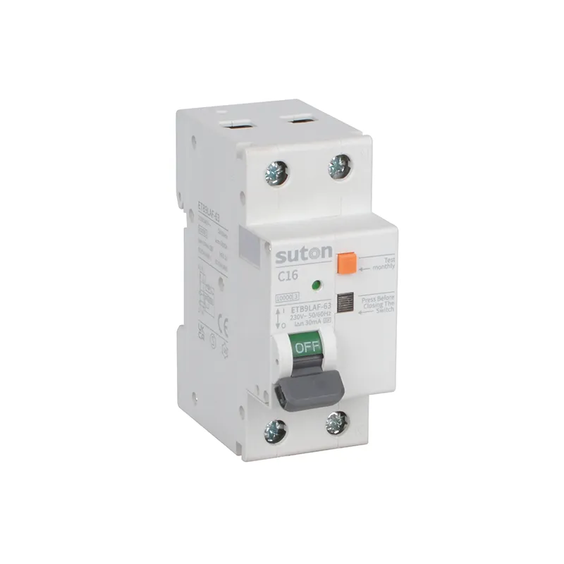
Where modular motor-branch protection devices are under review, the public ETB9LAF-63 series arc fault detection device route may support an inquiry once the motor schedule and protective matrix are documented. Confirm exact offer, markings, instructions, and assembly interfaces before release.
Motor thermal records and trip discipline
Treat the motor schedule, trip-class basis, setting record, test evidence, and revision history as one handover package. Facilities that inherit the dossier can diagnose repeat events; facilities that inherit only a setting label tend to raise the dial at the first nuisance trip.
After any unexpected thermal trip, record the circuit, connected load, start sequence, ambient condition, and recent process change before reset. Compare the event against the approved duty data: a new cyclic load, a ventilation blockage, or a mechanical binding often explains the symptom faster than swapping the protective element by default.
When the motor branch is modified, update the schedule and coordination record before re-energizing. An added interlock, changed start method, or replaced driven machine changes thermal duty even when the nameplate current appears unchanged.
FAQ
What is thermal overload in a motor feeder?
It is the motor heating duty that the protection arrangement must coordinate with, using documented current, time, and operating conditions.
Is thermal overload the same as an overload relay?
No. This guide addresses duty, trip-class setting, and diagnosis; selecting an overload relay component requires separate model and coordination data.
Should a repeat trip be solved by raising the setting?
No. Record load, current, start timing, and thermal conditions first, then follow the authorized engineering review.
Why does ambient temperature matter for thermal overload?
Panel temperature and device grouping can change thermal operating conditions from those assumed in the reference installation or protection study.
What does trip class depend on?
It depends on the documented motor start and the authorized protection-coordination basis, not on a generic preference or field habit.
What belongs in a motor thermal overload RFQ?
Include motor nameplate data, measured current, start method and duration, ambient conditions, trip history, circuit arrangement, standards requested, and quantity.