The choice of busbar trunking vs cable distribution should follow the facility layout, load pattern, fault duty, expansion strategy and installed cost. Busbar trunking can suit repeated load take-offs along a planned route, while cables can suit dispersed destinations, complex routing and selected point-to-point feeders. Neither is automatically cheaper, more efficient or safer in every building. Compare complete systems on the same electrical and environmental requirements, including supports, protection, installation access and future shutdowns. This guide gives industrial purchasers a practical way to make that comparison without relying on broad marketing claims.
Define the two complete distribution options
A busbar trunking system is an engineered distribution system with conductors, enclosure, joints and associated components. A complete proposal may include feeder sections, bends, expansion provisions, tap-off units and mounting hardware. A cable proposal includes the conductors and their insulation, termination systems, containment, cleats or supports and protective arrangements. Comparing only the price of a straight busway section with a length of cable leaves out substantial parts of both designs.
IEC 61439-6 addresses low-voltage busbar trunking systems. Confirm the edition and requirements adopted for the project and obtain the relevant manufacturer's evidence. An enclosed distribution assembly inside a panel is not automatically an interchangeable substitute for a building-length busbar trunking system. Define the intended installation before asking a supplier to confirm suitability.
Start with a load and route schedule
List each load, expected current, starting behavior, operating hours and likely future change. Separate a continuous process feeder from a production line with regularly relocated machines. Mark the actual route, changes of direction, floor crossings, obstructions and access zones. A short direct route can favor a different solution from a congested route with many changes in level, even when both supply the same connected load.
Do not equate spare outlets with spare electrical capacity. Future tap-off positions are useful only when the feeder, protective devices, neutral, fault rating and temperature limits also support the intended expansion. Define an agreed future load scenario and include it in both alternatives. Otherwise one bidder may price present duty while another prices expansion, making their quoted current ratings and costs difficult to compare.
Compare continuous-current duty under actual conditions
Use the same ambient conditions, installation orientation, loading assumptions and enclosure requirements for both options. Cable ampacity depends on installation method and environmental factors; a busbar system also has declared service conditions and limitations. Grouping, ventilation, surrounding heat sources and harmonic loading can affect the final design. A nameplate current alone does not settle suitability for a specific factory environment.
The busbar current-rating guide explains why conductor area is only one input. For nonlinear single-phase loads, include the neutral busbar sizing review in the design discussion. Both cable and trunking alternatives must provide an appropriate neutral arrangement, rather than treating the neutral as an afterthought once the phase conductors have been chosen.
Calculate voltage drop using the actual topology
For a balanced three-phase feeder, an approximate voltage-drop expression is ΔV = √3 × I × L × (R cos φ + X sin φ). Use line current I in amperes, one-way route length L in kilometres, and suitable resistance R and reactance X in ohms per kilometre at the relevant conditions. The result is volts. Manufacturer impedance data and the actual distribution topology are needed; a single total load placed at the far end can misrepresent distributed take-offs.
As an illustrative calculation, 200 A over 0.05 km with R = 0.10 ohm/km, X = 0.08 ohm/km and power factor 0.9 gives about 2.16 V using that simplified expression. These are assumed teaching inputs, not SUTON product values. Evaluate each loaded segment and relevant starting condition in the project model. Check any voltage requirement against the applicable installation rules and equipment needs.
Verify fault protection and structural restraint
Both alternatives must suit the available fault duty and the protective-device arrangement. For busbar trunking, review the declared system rating and any conditions attached to joints and tap-offs. For cable systems, include conductor thermal duty, terminations, support and cleat performance as applicable. A breaker capable of interrupting the fault does not independently prove that every downstream mechanical component withstands the event.
IEC 60865-1 describes AC short-circuit mechanical and thermal effects and directs readers to other relevant methods for cables and insulated conductors. Use the appropriate engineering basis for each alternative. Compare the evidence boundaries rather than assuming one construction avoids fault-force analysis because its conductors are enclosed or because its route uses flexible cables.
| Decision factor | Busbar trunking proposal | Cable distribution proposal |
|---|---|---|
| Route | Count sections, bends and joint access | Check pulling space, containment and terminations |
| Take-offs | Confirm compatible units and spare capacity | Define branch feeders and termination scope |
| Current duty | Obtain ratings for actual service conditions | Calculate ampacity for the installation method |
| Fault duty | Verify system and tap-off conditions | Verify conductor, support and termination duty |
| Expansion | Model isolation and capacity of added loads | Model new routes and additional circuits |
| Cost | Include supports, joints, tap-offs and labor | Include containment, cleats, glands and labor |
Assess installation work and future changes honestly
Repeated take-off locations along an accessible route can make a modular distribution system attractive. However, bends, transitions, access to joints, lifting provisions and support installation can dominate work on a complicated route. A cable solution may adapt readily to some obstacles but can require more pulling space, termination labor or containment. Request a route survey and installation method for each alternative before assigning labor savings.
Future changes need a safe isolation and work plan. Do not assume a plug-in tap-off can be inserted, removed or serviced while energized; follow the manufacturer's instructions and site rules. Ask how an added load affects shutdown duration, protection coordination and documentation. A design that saves installation time today can create a difficult production outage later if access and spare capacity were never planned.
Compare losses and lifetime cost on equal assumptions
Resistive energy loss depends on current, resistance and operating time; alternating-current distribution may also require other loss components. Ask for comparable manufacturer data at the expected operating conditions. For a simple constant-load illustration, a 100 W difference sustained for 4,000 hours represents 400 kWh per year. Convert that to cost using the site's actual tariff and operating profile, not an advertised universal saving percentage.
Build the cost comparison from equipment, supports, containment, installation, inspection, maintenance access, spares and foreseeable modification work. Show assumptions for route length and future loads next to the totals. If shutdown cost is included, identify the outage scenario and responsible operational team. Avoid assigning an invented production-loss value merely to make one option appear financially superior.
Check environment, fire strategy and maintenance access
Specify dust, moisture, corrosion, mechanical impact and cleaning conditions. An ingress-protection statement applies to an identified configuration and installation condition; joints, tap-offs and unused openings must be addressed. Fire performance, compartment penetrations and continuity of essential services require the applicable building and project requirements. A metal enclosure alone does not establish fire resistance, circuit integrity or a fire-stop system approval.
Plan inspection access before filling the route with adjacent services. Teams need a way to locate joints, identify circuits and follow the approved maintenance instructions. Ask which components are serviceable, how replacements are obtained and which inspections require isolation. Neither cable insulation nor a closed trunking enclosure removes the need for an appropriate maintenance strategy for the complete installation.
Review the actual SUTON product boundary
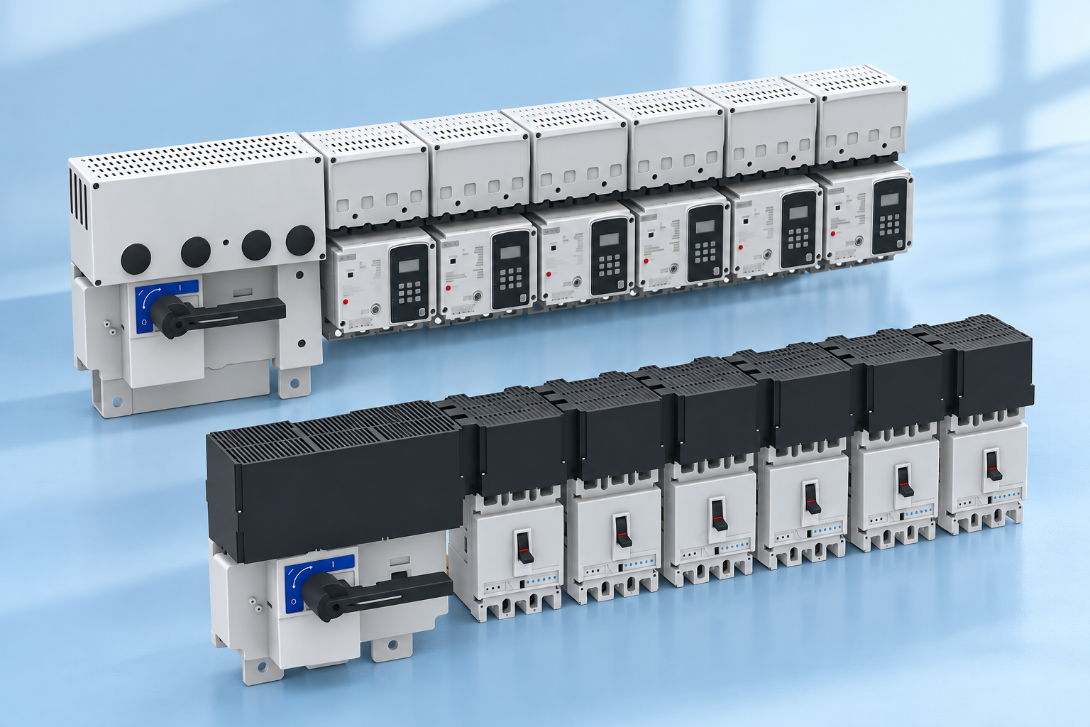
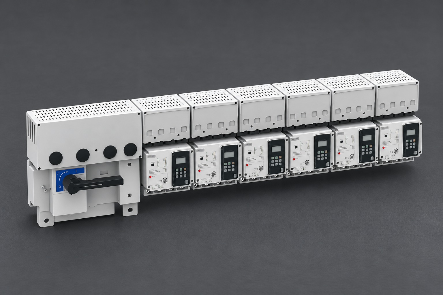
The SUTON ETFZX enclosed busbar system is a relevant starting point for discussing enclosed distribution assemblies and outgoing circuits. Ask SUTON to confirm the intended application of the specific configuration. Its exterior illustration should not be read as evidence of a building-length trunking range, a particular cable replacement capability or an unverified installation standard declaration.
Coordinate the distribution choice with copper versus aluminum busbar considerations. Material, enclosure design and connection arrangements can influence a proposal, but they do not establish a universal winner. Submit the single-line diagram, load schedule, route and environment with the enquiry so a supplier can distinguish an appropriate product from an arrangement outside its documented scope.
Use a clear tender and acceptance process
Issue the same design inputs to both bidders. Require a marked route, component schedule, service conditions, fault-duty evidence, installation scope and exclusions. Ask each bidder to identify the proposed expansion method and the limits that would trigger redesign. Resolve assumptions about supports, terminations and civil works before comparing totals, because these are frequent sources of differences between apparently similar quotations.
At acceptance, match the delivered components to the approved system identity. Retain drawings, ratings, inspection results and instructions in one handover package. Record substitutions and obtain the required assessment before installation. A fair comparison ends with a maintainable system whose documented limits match the facility, rather than with a winning quotation whose missing components are discovered during commissioning.
Frequently asked questions
Is busbar trunking always cheaper than cables?
No. The result depends on route geometry, number of take-offs, conductor requirements, installation labor, supports, terminations and future modifications. Compare the complete installed systems using the same load and environmental assumptions. A straight-section price alone cannot establish the lower-cost option for a facility.
Which option is better for future machine moves?
A suitable modular trunking route can help when loads move along predictable locations, provided spare capacity, compatible tap-offs and access exist. Cables may suit widely dispersed or irregular destinations. Evaluate the actual relocation scenario, isolation requirements and protection changes before selecting the distribution method.
Can the ETFZX exterior photo prove trunking performance?
No. A product image identifies visible construction only. Obtain the specific product application statement, ratings, installation instructions and applicable verification evidence. Confirm that the proposed configuration serves the intended distribution role instead of inferring building-system performance from the appearance of an enclosed panel assembly.
Educational video
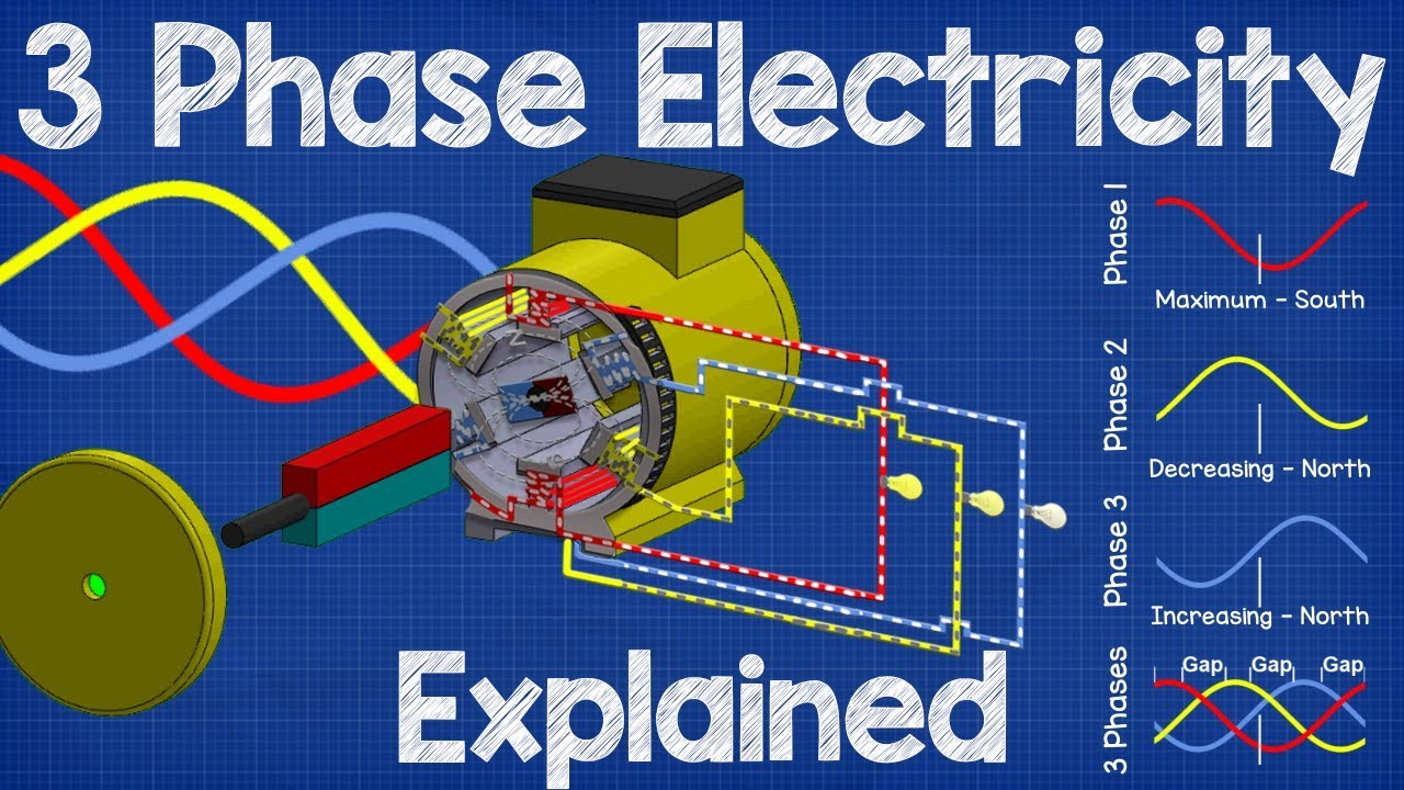
How Three Phase Electricity works – The basics explained by The Engineering Mindset. This neutral educational video explains the three-phase supply underlying the feeder discussion. It does not rank products or approve either distribution option.