


A motor starter is a motor-control arrangement — not a single catalogue label that settles every protective function in the branch.
Panel builders use the term when they need documented run/stop control, overload setting, control-circuit interfaces, and a clear boundary with branch short-circuit protection. Start from the approved motor schematic and device schedule, record the duty and control inputs that drive device choice, and only then compare starter quotations.
Important: This guide structures motor-control specification for LV panels in line with assembly integration practice in IEC 61439-1 and motor-starter product scope in IEC 60947-4-1. It cannot approve a starter marking, overload setting, or coordination result where motor data, fault duty, control logic, or branch protection references are missing — hold those inputs for engineering review before procurement.
Part 1. Turn a motor starter request into documented panel inputs
Ask “which starter for this motor?” and you are really asking for a controlled input set. The starter applies and removes power under the approved control sequence; it does not, by itself, prove that the branch short-circuit protective device, overload element, isolator, and control circuit are correctly assigned and coordinated.
Use the table below to turn a short enquiry into reviewable documentation before any supplier comparison begins.
| Selection factor | Why it matters for the panel | Send with quote |
|---|---|---|
| Motor nameplate data (voltage, current, duty class) | fixes the thermal and electrical starting envelope | yes |
| Driven-load behavior and inertia | drives starting method and acceleration expectations | yes |
| Start frequency and expected run time | affects thermal duty on overload and contactor | yes |
| Supply arrangement and control voltage | fixes coil, auxiliary, and interlock interfaces | yes |
| Approved single-line and motor-control schematic | shows every assigned protective and control role | yes |
| Branch short-circuit protective device reference | separates SCPD duty from starter control duty | yes |
| Fault-study or available-fault reference | supports coordination review, not nominal-current matching | when applicable |
| Enclosure, ambient, and mounting interface | affects device family and terminal access | yes |
| Required start/stop/interlock sequence | defines control contacts and safety-related circuits | yes |
| Standards requested and quantity | fixes approval scope and procurement batch | yes |
Projects that skip the table often receive quotations built on nominal current alone. That produces a second procurement cycle once coordination, control interfaces, or commissioning scope is challenged on site.
Part 2. Separate starter control from branch and motor-circuit protection
A motor starter controls the motor’s run and stop function under the approved sequence. A live motor circuit protector protects the energized motor branch against the fault duties assigned to it in the design. Those roles can appear in one engineered arrangement, but they are not interchangeable labels.
| Function | Primary duty in the motor branch | Common planning mistake |
|---|---|---|
| Contactor / starter switching device | apply and remove power under control logic | treating contactor rating as proof of short-circuit protection |
| Overload relay or integrated overload | respond to sustained overload per approved setting | selecting a range without the motor duty and reset method |
| Branch SCPD (MCB, MCCB, fuse, MCP) | interrupt fault current assigned upstream or in branch | upsizing only by nominal current without coordination data |
| Isolator / disconnect | visible break or isolation for maintenance | omitting from the motor-control dossier |
| Control circuit protection | protect the control supply and auxiliaries | sharing neutrals or supplies that break traceability |
Device-level branch protection and motor-circuit protector selection steps live in the circuit breaker guide and the live motor circuit protector guide. This article owns starter inputs, role separation, and coordination review — not a repeat of those device guides.
Where a design combines starter, overload, and branch protection, record the order of protective elements and which device owns each test during commissioning. Service teams should be able to identify the tripped element without disassembly.
Part 3. Record motor and control inputs before specification
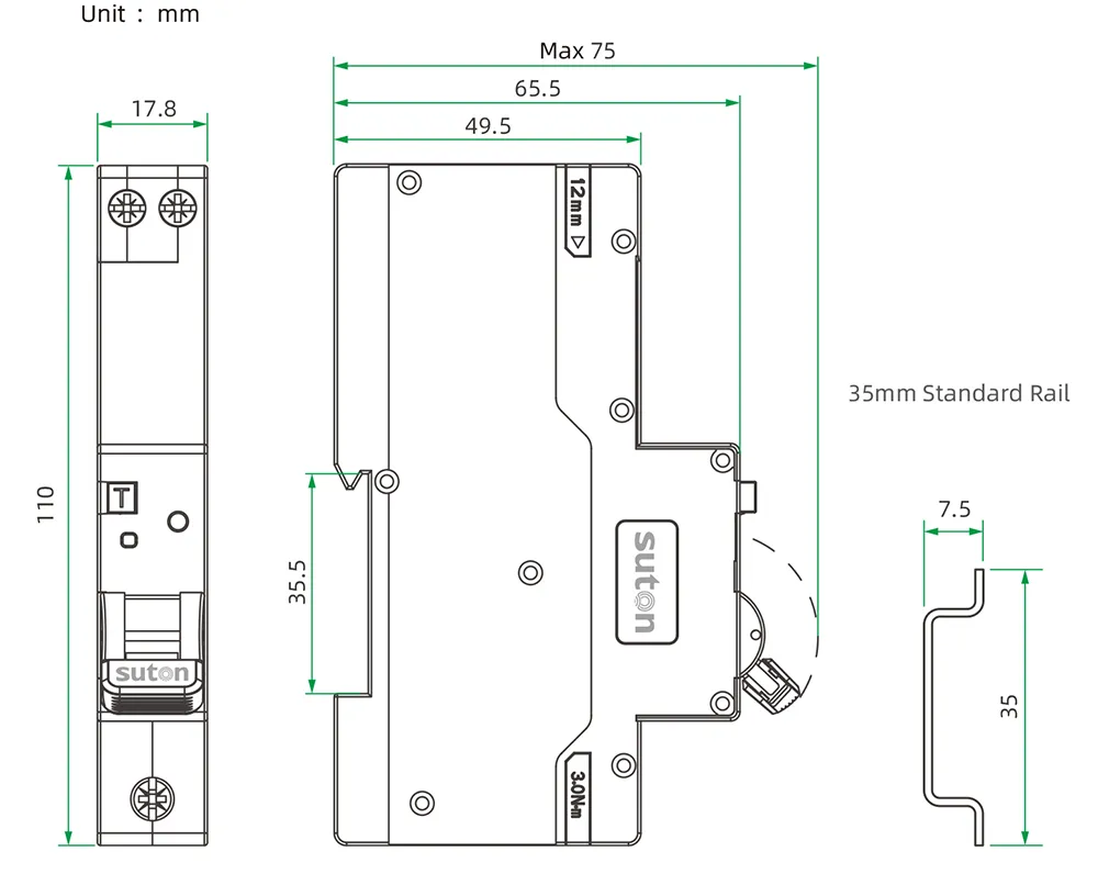
Begin with motor nameplate data, driven-load behavior, start frequency, expected run time, supply characteristics, control voltage, stopping method, and ambient conditions. Add the single-line diagram, motor-control schematic, cable route, enclosure arrangement, and any process interlocks.
Confirm whether the motor sits in a sequence with other loads and whether an automatic restart has operational or safety consequences. The schedule must identify the exact switching device, overload element, branch SCPD, and control-circuit protection — not only a contactor current rating.
Reserve module positions, terminal orientation, bending space, and door clearance from the schematic before the enclosure layout is frozen. A device that fits electrically but cannot be wired, set, or tested during commissioning becomes a latent compliance gap.
Part 4. Review protection, overload, and coordination evidence
Keep the branch short-circuit protective device, overload protection, switching device, control circuit protection, and isolating means visible on the drawing. Review the proposed arrangement against available fault duty, motor starting behavior, and manufacturer coordination documentation for the exact device combination.
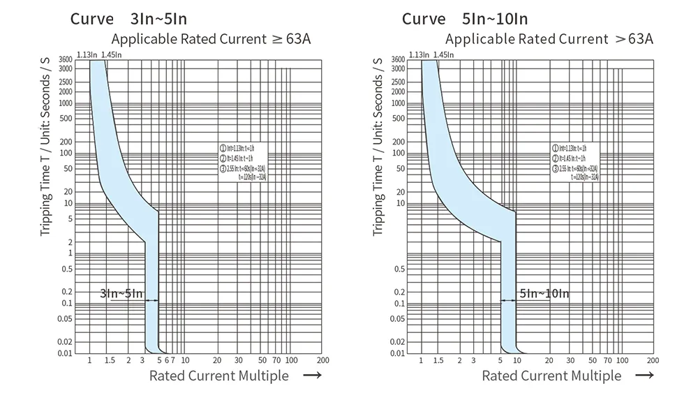
Do not infer a coordination result from matching nominal current numbers on unrelated datasheets. A starter marked for a motor current range does not automatically coordinate with an upstream breaker chosen by appearance or a generic curve letter.
Where the project references molded-case or modular branch devices, retain the manufacturer’s coordination tables or test references with the panel dossier. Commissioning and later expansion both depend on that evidence remaining traceable to the installed markings.
Starting methods matter: direct-on-line, star-delta, soft starter, and variable-speed drive arrangements change the current profile seen by overload and branch devices. Record the approved starting method on the schedule so settings and protective devices are reviewed against the same duty.
Part 5. Verify installation and commissioning against the drawing
Before energization, verify terminal assignments, control voltage, coil markings, overload setting procedure, protective-device arrangement, earthing, enclosure clearances, and approved conductor terminations against the released drawing.
Commission the permitted start, stop, trip, restart, and interlock sequences under the project procedure. Exercise overload trip and reset only with the authorized method and without defeating interlocks or bypassing the protective path.
Record device markings, configured overload setting, wiring checks, control-circuit tests, and any approved logic dependencies in the motor-control dossier. Unexpected trips during commissioning should capture load state, switching context, and setting values before devices are replaced by default.
Periodic service should treat setting changes as controlled events: update the dossier when a permitted overload adjustment or device swap occurs so maintenance starts from documented facts.
Part 6. Route an evidence-based SUTON inquiry
Send with the inquiry:
- approved motor single-line and control schematic with every assigned role marked
- motor nameplate data, load behavior, and starting method
- start frequency, run-time expectations, and restart permissibility
- supply and control voltages, interlock list, and interface signals
- branch SCPD or MCP reference and fault-study citation when applicable
- enclosure class, ambient limits, and mounting interface constraints
- standards requested, accessories, labeling expectations, and quantity
Require suppliers to declare the exact offered marking, overload setting range, installation instructions, accessories, and any exceptions against the controlled documents. Hold the engineering decision when motor duty or coordination evidence is incomplete — a quotation against undefined motor data cannot preserve the design intent.
Fit Boundary: this guide structures motor-starter specification inputs for LV panels. It does not decide national rule applicability, does not replace a coordination study, and cannot approve a starter where motor data, fault duty, control logic, or branch protection references are missing. Escalate those gaps to the design authority before the package is priced.
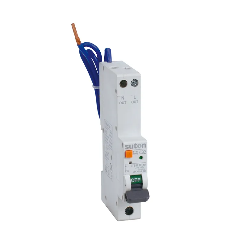
SUTON’s modular DIN rail products category is a public route for discussing modular protection and isolation elements after the buyer has documented the required functions and project conditions. It is not treated here as proof that every listed product satisfies the motor duty or coordination evidence for a specific branch.
Once the motor schedule and schematic are approved, send the controlled documents through Contact SUTON for a documented product-route review. Public pages do not fix marking, setting range, coordination, or installation exceptions for a specific panel — those remain project-specific confirmations.
Compare quotations against the same documented requirements and retain the final device schedule with the assembly record.
Motor-control dossier and service discipline
Treat the motor schematic, device schedule, coordination references, setting records, and test results as one handover package. Facilities that inherit the dossier can maintain and expand the motor branch with traceability; facilities that inherit only a contactor label tend to rebuild the review from scratch at the first trip event.
When the panel is modified, update the schematic and schedule before energizing new motor circuits. An added motor, changed starting method, or swapped branch device alters coordination and commissioning scope even when nominal ratings appear unchanged.
After any unexplained trip, record the circuit, configured overload setting, connected load, and recent switching activity before reset. Patterns across records often distinguish a setting issue, a coordination gap, or a load condition the original specification did not capture.
FAQ
What is a motor starter?
It is a motor-control arrangement used to start and stop a motor according to the approved circuit and operating sequence, typically including switching and overload elements defined by the design.
Is a motor starter a live motor circuit protector?
No. The starter controls the motor; the live motor circuit protector has a separate assigned protective role in the energized branch. See the motor circuit protector guide for branch protector selection context.
What motor data is needed for starter selection?
Provide nameplate data, driven-load behavior, starting duty, run time, supply, control voltage, starting method, and the approved schematic — the Part 1 table lists what to send with a quote.
Does a contactor provide short-circuit protection?
Do not assume that it does. Review the branch protective arrangement and exact coordination documentation for the installed combination.
What should be tested during commissioning?
Verify the documented control sequence, interlocks, protective arrangement, terminations, markings, overload setting, and authorized trip behavior; archive results in the motor-control dossier.
What belongs in a motor starter RFQ?
Include motor duty, supply and control data, starting method, branch protection reference, fault-study citation when applicable, enclosure and interfaces, standards requested, and quantity.