


Overload relay selection is a motor-branch documentation task — not a catalogue current range. The relay implements the overload function assigned to the circuit, but only after motor nameplate data, starting duty, reset logic, and coordinated branch protection are recorded on the drawing. A relay label alone cannot settle short-circuit duty, starter interface, or the setting basis the commissioning file will audit later.
Start with the approved motor-control schematic and single-line diagram. Name the motor load, the upstream branch protective device, the switching or starter arrangement, and the reset method the operator must follow. Only then compare relay families against the documented duty rather than a nominal ampere band from a price list.
Important: This guide structures overload-relay inputs for motor branches in line with assembly integration practice in IEC 61439-1. It cannot approve a relay marking, trip setting, or coordination result where motor data, fault-duty references, or control logic are absent — hold those inputs for engineering review before procurement.
Part 1. Turn overload relay selection into a motor branch review
Ask “which relay range fits this motor?” before the drawing is controlled, and the question collapses into a guess. An overload relay belongs to a motor-control arrangement that must show the motor duty, the permitted trip and reset behavior, the starter or contactor interface, and the branch protective reference the design authority accepted.
Treat the relay as one element in that arrangement, not as the whole motor circuit. The schematic should already show where overload sensing sits relative to the switching device, which contacts feed the control circuit, and whether manual or automatic reset is allowed for the process. Projects that skip that record often reorder relays after commissioning finds a mismatch between the installed setting and the actual start profile.
The review output is a controlled input list tied to the drawing — not a part number copied from a motor nameplate in isolation. When several motors share a panel, give each branch its own documented duty block so a later substitution does not inherit another machine’s assumptions.
Part 2. Separate overload relay duty from branch protection
An overload relay addresses the thermal or overload function assigned to the motor circuit. The branch short-circuit protective device — breaker, fuse, or combination unit — addresses fault duties defined by the project study and product standard. Those roles stay distinct even when manufacturers offer coordinated kits.
| Protective or control element | Primary role on the motor branch | Planning consequence |
|---|---|---|
| Branch SCPD (MCB, MCCB, fuse) | Short-circuit and defined overcurrent protection | Does not replace documented overload setting and trip behavior |
| Overload relay or integrated overload | Motor overload function per approved setting method | Requires motor duty, trip class, and reset logic on the drawing |
| Contactor or starter | Run, stop, and control sequencing | Interface and coil data must match the relay and control schematic |
| Isolator or disconnect | Safe isolation for maintenance | Separate from overload tripping and restart permissions |
Keep this matrix visible when buyers compare “motor protection” quotations. Device-level breaker context lives in the circuit breaker guide; feeder-level short-circuit frames appear in the MCCB breaker guide. This article owns overload-relay inputs, setting evidence, and procurement boundaries — not the full branch protection calculation.
Where starter assemblies combine switching and overload elements, record which function each marking covers and which manufacturer instructions govern the setting procedure. Commissioning must show the approved combination, not an assumed equivalence between similar current ratings.
Part 3. Record the motor inputs that set relay selection
Capture nameplate full-load current, voltage, phase arrangement, service factor, and insulation class. Add driven-load behavior: constant torque, variable torque, cyclic duty, or frequent starts. Note ambient temperature, enclosure ventilation, altitude derating if applicable, and whether the motor restarts automatically after a trip.
Control inputs matter as much as thermal ones. Record control voltage, the starter type, auxiliary contact arrangement, remote reset permissions, and any interlock that must remain closed before restart. If the motor feeds a process step with safety consequences, document whether automatic restart is prohibited even when the relay allows it.
Link these inputs to the single-line diagram and motor-control schematic before any catalogue comparison. The motor starter guide helps separate starter control duties from branch protection; the relay selection still needs its own duty block on the schedule.
Part 4. Control settings, trip class, and coordination evidence
Setting an overload relay is an engineering act tied to manufacturer instructions and the motor’s thermal withstand — not a preference for the highest available dial position. Trip class, when applicable, must align with the documented start duration and acceleration profile. Changing class or setting without that basis invites nuisance tripping or under-protection.
Coordination review keeps four names on one page: the branch SCPD, the switching device, the overload element, and the isolating means. Compare the proposed combination against the available fault duty and the manufacturer’s coordination data for the exact catalog numbers shown on the drawing. Matching nominal currents is not a coordination certificate.
At assembly, verify the delivered relay marking, setting range, terminal assignment, and reset hardware against the released schedule. During commissioning, exercise the approved trip and reset sequence under the project method and record the configured setting, test date, and operator. Preserve that record in the motor-control dossier next to the schematic the design authority signed.
Part 5. Build an RFQ that preserves motor protection intent
A motor-branch RFQ is a package, not a relay range line item.
| RFQ input | Why it matters |
|---|---|
| Motor nameplate and driven-load description | fixes thermal duty and setting basis |
| Start frequency, duration, and acceleration profile | validates trip class and setting method |
| Approved single-line and control schematic | shows relay position and interfaces |
| Branch SCPD reference and fault-study citation | anchors coordination review |
| Required trip behavior and reset method | fixes operator and safety constraints |
| Control voltage, auxiliary contacts, and interlocks | fixes wiring and logic scope |
| Ambient, enclosure, and mounting interface | fixes derating and mechanical fit |
| Standards requested, quantities, and accessories | fixes approval and assembly scope |
Require suppliers to declare the exact offered marking, setting range, installation instructions, and any deviation from the documented arrangement. Hold the engineering decision when motor data or coordination references are incomplete — a quotation against an undefined schematic cannot preserve protection intent.
Fit Boundary: this guide structures overload-relay selection inputs for motor branches in LV assemblies. It does not perform fault studies, does not approve settings without motor and coordination data, and cannot substitute for the branch SCPD role assigned by the design. Escalate missing motor, fault-duty, or control-logic inputs to the design authority before the relay is priced or ordered.
Part 6. Route an evidence-based SUTON inquiry
SUTON’s modular DIN rail products category is a public route for discussing modular protection and control families after the buyer has defined the motor branch functions and project conditions. It is not treated here as proof that every listed item satisfies a specific overload-relay duty for every motor.
Once the motor schedule, schematic, and branch protection reference are controlled, send those documents through Contact SUTON for a documented product-route review. Public pages do not fix relay marking, setting range, coordination, or installation exceptions for a named motor — those remain project-specific confirmations.
For adjacent motor-protection context, cross-read the motor starter guide before mixing control and overload elements in one schedule. Hold each supplier quotation against the same controlled schematic and motor duty block, and file the accepted schedule with the motor-control dossier.
Product recommendation boundary
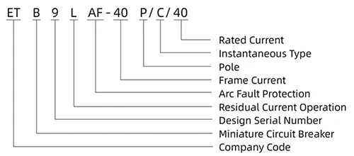
The modular DIN rail products category is the appropriate SUTON product recommendation route after the buyer has defined the required motor-branch functions and project conditions. It is not a default approval of a particular relay or starter combination.
Where modular motor-control and protection elements are under review alongside the documented schematic, use the public catalogue route to open an inquiry — then confirm exact offer, markings, setting instructions, and assembly interfaces before release. Do not treat illustrative product photography as proof of overload-relay suitability for a named duty.
Motor branch dossier and service discipline
Treat the motor schematic, relay setting record, coordination references, and commissioning results as one handover package. Facilities that inherit the dossier can service the branch; facilities that inherit only a relay dial setting tend to rediscover coordination gaps at the first unexplained trip.
After any overload operation, record motor current trend, load state, start sequence, and recent mechanical changes before reset. Compare the event against the approved duty block: a trip during acceleration, after steady run, or after a process change each points to different checks. Automatic restart attempts without that record can mask a driven-machine fault.
When the motor or its control arrangement changes, update the schematic and setting record before returning to service. A replacement motor with different nameplate data, a new VFD interface, or a changed start frequency invalidates a previous relay setting even when the physical relay remains on the rail.
FAQ
What does an overload relay protect?
It implements the documented motor overload function for the branch when selected, set, and wired according to the approved design and manufacturer instructions.
Is an overload relay a branch short-circuit protective device?
No. It does not replace the SCPD assigned to the energized motor branch; keep fault-duty and overload duties distinct on the drawing.
What motor data is needed to select an overload relay?
Provide nameplate current, driven-load behavior, start profile, ambient and enclosure conditions, control voltage, starter interface, and reset requirements tied to the schematic.
Does an overload relay replace a breaker or fuse?
No. The branch SCPD retains its assigned short-circuit and overcurrent role; the relay addresses the overload function defined for the motor circuit.
What should commissioning record for an overload relay?
Record relay marking, configured setting, wiring verification, approved trip and reset test, control dependencies, and the date and method reference.
What belongs in an overload relay RFQ?
Include motor and load data, schematic references, branch SCPD and fault-study citations, trip and reset requirements, control interfaces, environment, standards, and quantity.