


A busbar system is bought on documented duty — current, withstand, insulation, and mechanics — and proven at assembly level, not by bar size alone.
Panel builders use the term when they need to distribute current inside an assembly or along a route: panel busbars versus enclosed busbar trunking, electrical ratings, mechanical design, and assembly verification. Start from the fault study and layout drawing, then compare configurations against the same duty package.
Important: This guide structures busbar-system selection for LV assemblies in line with integration practice in IEC 61439-1. It cannot approve a busbar rating, bracing design, or configuration where load data, fault duty, ambient conditions, or the layout drawing are missing — hold those inputs for engineering review before procurement.
Part 1. Turn a busbar system request into documented duty inputs
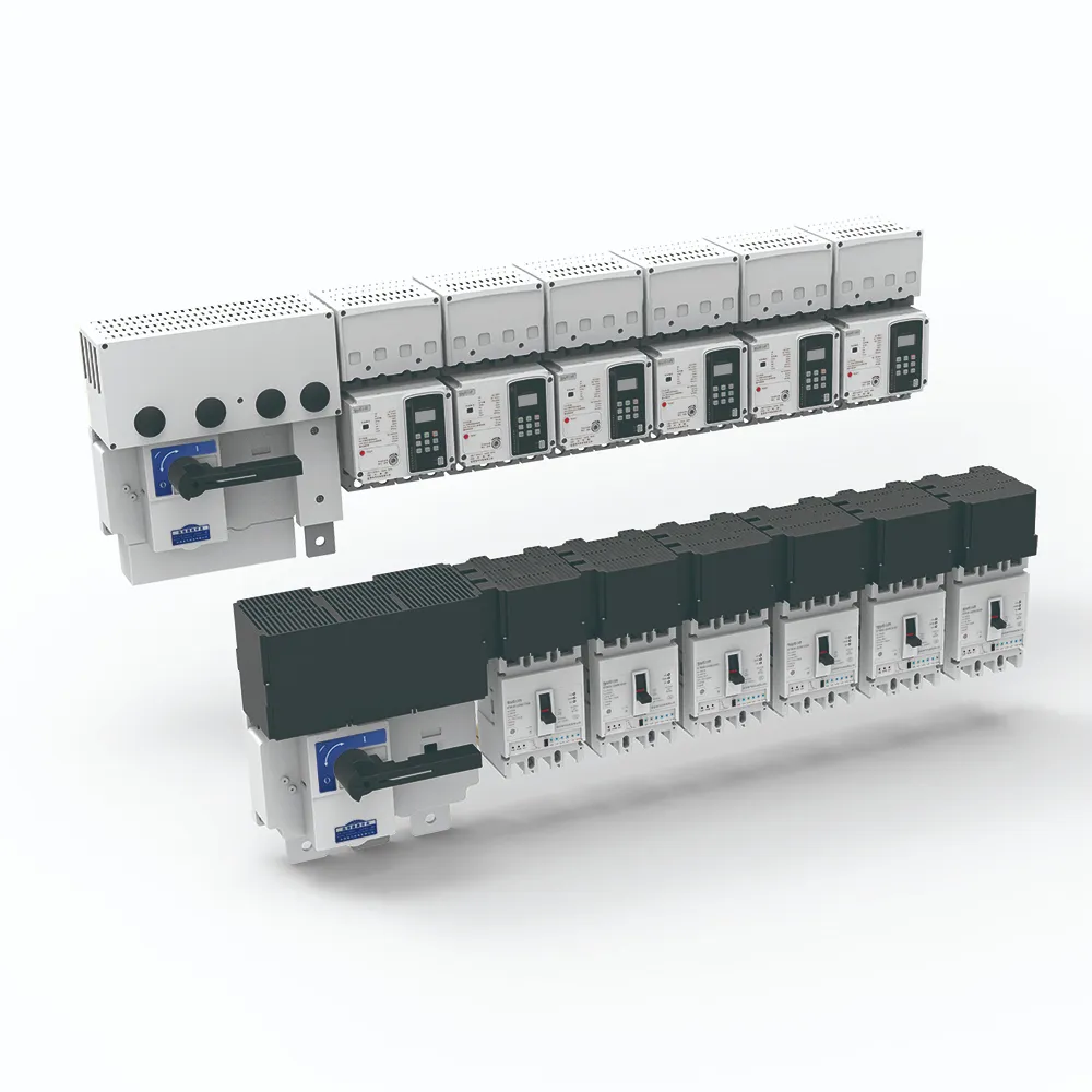
Between the incomer and the outgoing devices, the busbar system carries and distributes the assembly’s full current. It includes the bars themselves plus supports, insulation, joints, and tap-off arrangements — a system, because each element limits the others. Boards that fail thermally or during faults usually failed at a joint or a support, not in the middle of a healthy bar.
The table below records busbar-system duty inputs that configuration quotations must answer against the same fault study.
| Selection factor | Why it matters for the busbar system | Send with quote |
|---|---|---|
| System type (panel bars or enclosed trunking) | fixes product family and evidence package | yes |
| Voltage and insulation coordination needs | fixes clearances, creepage, and bar geometry | yes |
| Continuous current with ambient and enclosure data | fixes conductor sizing basis | yes |
| Fault withstand (peak and short-time) from the study | fixes bracing and support spacing | yes |
| Layout drawing with lengths and tap-off positions | fixes configuration and joint count | yes |
| Material preference (copper or aluminium) | fixes weight, joints, and cost trade-offs | yes |
| Environment (corrosion, humidity, access) | fixes coating and enclosure choices | yes |
| Verification evidence and record format required | fixes compliance scope | yes |
| Protective devices protecting the bars | fixes coordination context | yes |
| Standards requested and quantity | fixes approval scope and batch size | yes |
Projects that skip the table often receive quotations built on a bar cross-section alone. That produces a second procurement cycle once fault duty, tap-off geometry, or verification evidence is challenged during assembly.
Board-level context sits in the distribution board sizing guide; section anatomy for populated boards is covered in the panel board guide.
Part 2. Choose panel busbars versus enclosed busbar trunking
Two product families answer different distribution problems. The choice against cable distribution is a route-level decision: long runs with many tap-offs, or capacity that cables deliver awkwardly, are where enclosed systems earn their place.
| Aspect | Busbars inside a panel | Enclosed busbar trunking |
|---|---|---|
| Role | distribute within one assembly | distribute between areas or along a route |
| Engineering owner | panel builder within the assembly design | system manufacturer per configuration |
| Tap-offs | device connections inside the board | tap-off units along the run |
| Typical decision driver | board layout and fault duty | route, capacity, and flexibility versus cable |
| Evidence package | assembly verification records | system configuration data and instructions |
Record which family the project selected and why, so later extensions start from the same engineering assumption instead of reopening the route decision under time pressure.
Part 3. Fix electrical ratings from load and fault-study data
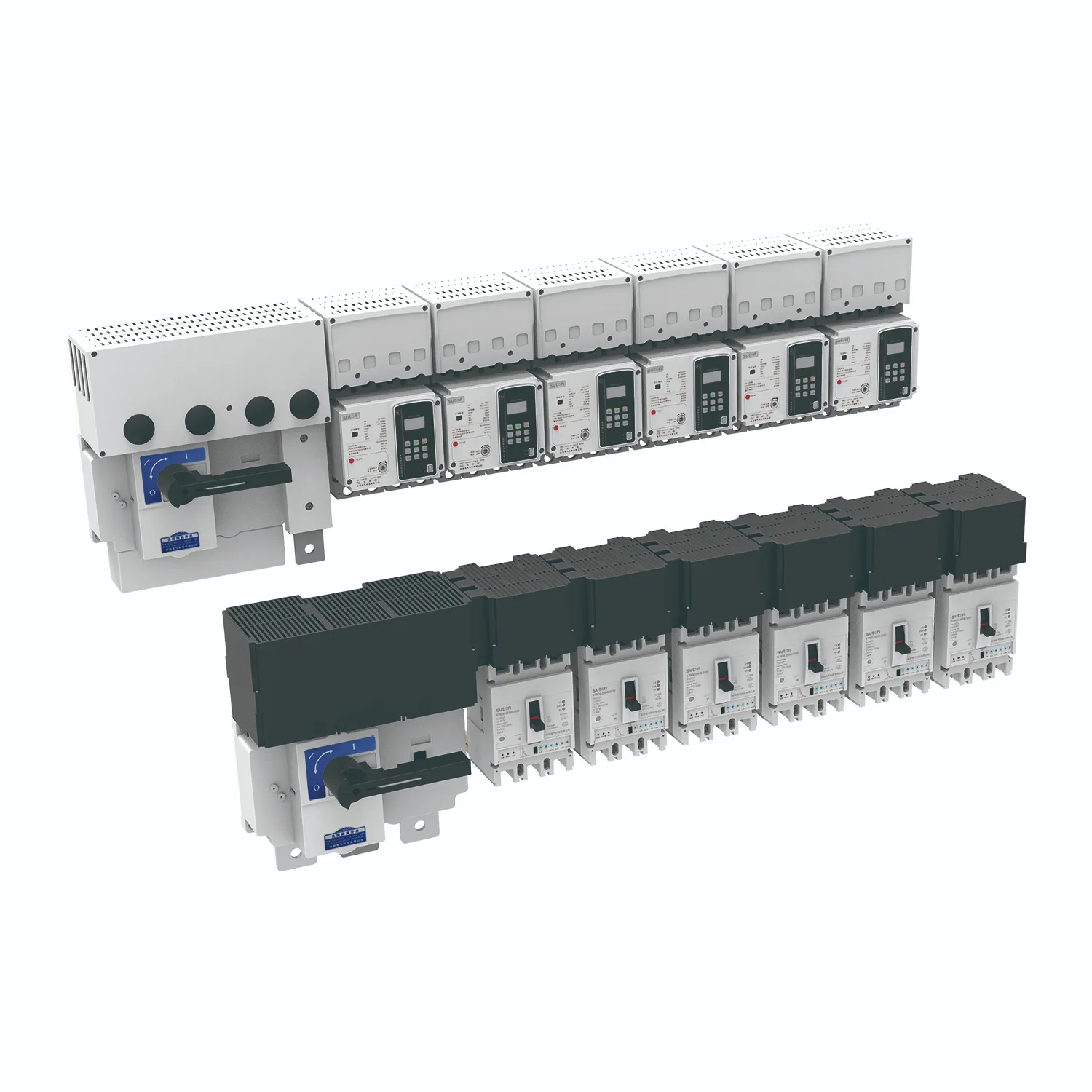
Three rating groups do the work. Continuous current at the real ambient temperature and enclosure condition — not the open-air figure — sets conductor size and ventilation needs. Fault withstand, expressed as peak and short-time values against the project fault study, sets bracing and support spacing. Insulation coordination — voltage, clearances, creepage, and any insulated-bar option — sets the geometry.
Material choice (copper or aluminium) then trades conductivity, weight, joints, and cost inside those ratings. Record the assumptions with the design so a future capacity question starts from facts rather than memory.
Do not infer a withstand result from matching nominal current numbers on unrelated datasheets. The evidence belongs to the assembled system for the installed configuration, not to a generic bar catalogue line.
Part 4. Resolve mechanical design for supports, joints, and expansion
Supports and joints convert electrical duty into mechanical reality. Support spacing resists fault forces; joint design — contact surfaces, plating, hardware, and torque — controls the millivolt drops that become hot spots years later. Thermal expansion over longer runs needs deliberate provision, and tap-off points need defined creepage and access.
Plan maintainability into the geometry: joint access for inspection, space for thermal scanning, and labeling that survives a decade. A bar that cannot be inspected will eventually be trusted blindly, which is how busbar failures stay hidden until they are expensive.
Procurement teams can help by refusing bar-only comparisons. Two offers with identical copper cross-sections can differ completely in supports, joints, insulation, and evidence; the cheaper bar with the weaker system is the expensive one over a decade of service.
Part 5. Verify busbar performance at assembly level
Busbar behavior is verified at assembly level under the applicable framework — temperature rise, short-circuit withstand, and clearances belong to the assembled system, with device data feeding the analysis. The incoming and feeder devices protecting the bars carry their own product-standard duties, as covered for large frames in the air circuit breaker guide.
During assembly, verification is practical: torque per the manufacturer’s instructions with a record per joint, contact surfaces prepared as specified, and supports positioned per the bracing design. Commissioning then adds inspection records and, where the operator uses it, a thermal-imaging baseline for future comparison.
Treat every modification as a system event. A new tap-off changes local forces, clearances, and thermal pictures, so it re-opens the affected part of the verification, and the panel dossier should say who approved it and on what basis.
Part 6. Route an evidence-based SUTON inquiry
Send with the inquiry:
- system type (panel bars or enclosed trunking) and layout drawing with tap-offs
- voltage, insulation coordination needs, and continuous current with ambient data
- fault withstand (peak and short-time) citation from the approved study
- material preference, environment, and access constraints
- protective device references and coordination expectations
- verification evidence and record format required
- standards requested and quantity
Require suppliers to declare the exact offered configuration, ratings basis, installation instructions, accessories, and any exceptions against the controlled documents. Hold the engineering decision when fault duty or layout data is incomplete — a quotation against undefined duty cannot preserve the design intent.
Fit Boundary: this guide structures busbar-system selection inputs for LV assemblies. It does not perform fault studies, does not verify assemblies, and cannot size a system where load data, ambient conditions, or the layout drawing are missing. Escalate those gaps to the design authority before the package is priced.
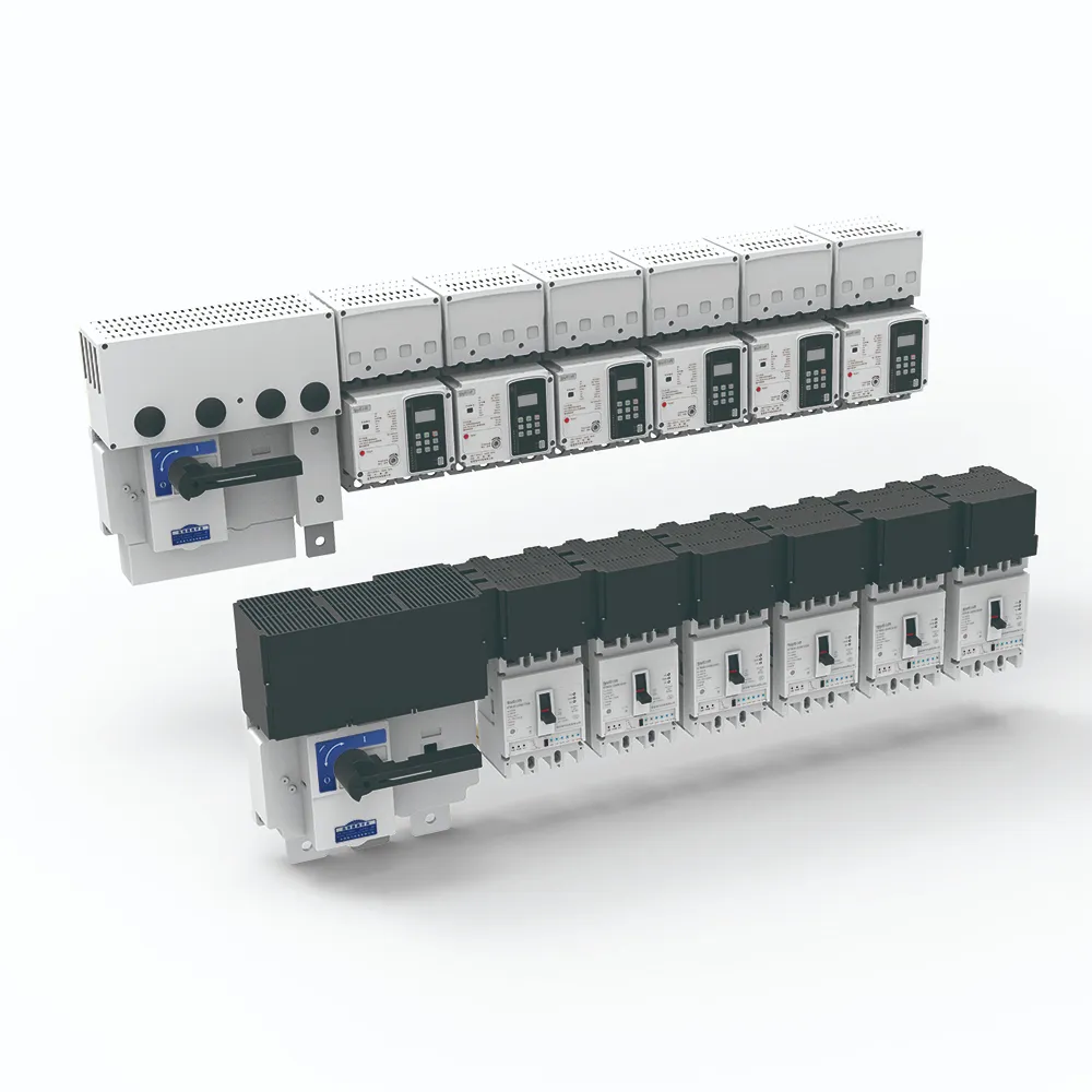
For a product recommendation starting point, review SUTON’s ETFZX low-voltage enclosed busbar system route for enclosed distribution duties; the devices protecting and tapping the system draw on molded case circuit breakers. Configuration ratings, dimensions, and certifications are model-specific — confirm them from datasheets against the project study.
Once the layout drawing and fault data are approved, send the controlled documents through Contact SUTON for a documented review. Public pages do not fix configuration ratings, dimensions, or verification coverage for a specific route — those remain project-specific confirmations.
Capacity planning across the system life
Design for the load the building will grow into, not only the day-one schedule. Spare tap-off provisions, conservative thermal margins, and documented assumptions make later extensions an engineering check rather than a replacement project.
When capacity questions arrive, work from records: the original ratings basis, joint torque logs, inspection history, and any thermal baselines. An upgrade decided against documented margins is quick; one decided against an undocumented bar means re-deriving the entire design under time pressure.
Compare systems against the same duty package, and keep the winning package in the contract file. Facilities that inherit the dossier can maintain and expand the busbar route with traceability; facilities that inherit only a bar label tend to rebuild the review from scratch at the first thermal event.
FAQ
What is a busbar system?
It is the conductor system — bars, supports, insulation, joints, and tap-offs — that carries and distributes current inside or between LV assemblies.
What ratings define a busbar system?
Continuous current under real ambient and enclosure conditions, fault withstand as peak and short-time values, and insulation coordination for the system voltage.
How is busbar short-circuit withstand verified?
At assembly level under the applicable framework, using the project fault study and the bracing design; the evidence belongs to the assembled system.
What is an enclosed busbar system?
A manufactured system packaging bars, insulation, and enclosure with tap-off provisions, used to distribute power along routes or between areas.
How are busbar connections checked during assembly?
Prepare contact surfaces as specified, torque joints per the manufacturer’s instructions with a per-joint record, and inspect supports against the bracing design.
What data belongs in a busbar system RFQ?
Provide system type, voltage and insulation needs, continuous current with ambient data, fault withstand, layout and tap-offs, material and environment, verification requirements, standards, and quantity — the Part 1 table lists what to send with a quote.