


Busbar connection work becomes predictable when the joint, enclosure interface, and released drawing are treated as one engineering package. Panel builders can then compare an enclosed LV busbar route on evidence rather than on a catalogue photograph.
Important: IEC 61439-1 places the verification responsibility on the completed low-voltage assembly. This guide helps structure interface data; it does not approve a joint rating, temperature rise, short-circuit withstand, or installation method without the project drawing and manufacturer instructions.
Part 1. What is a busbar connection?
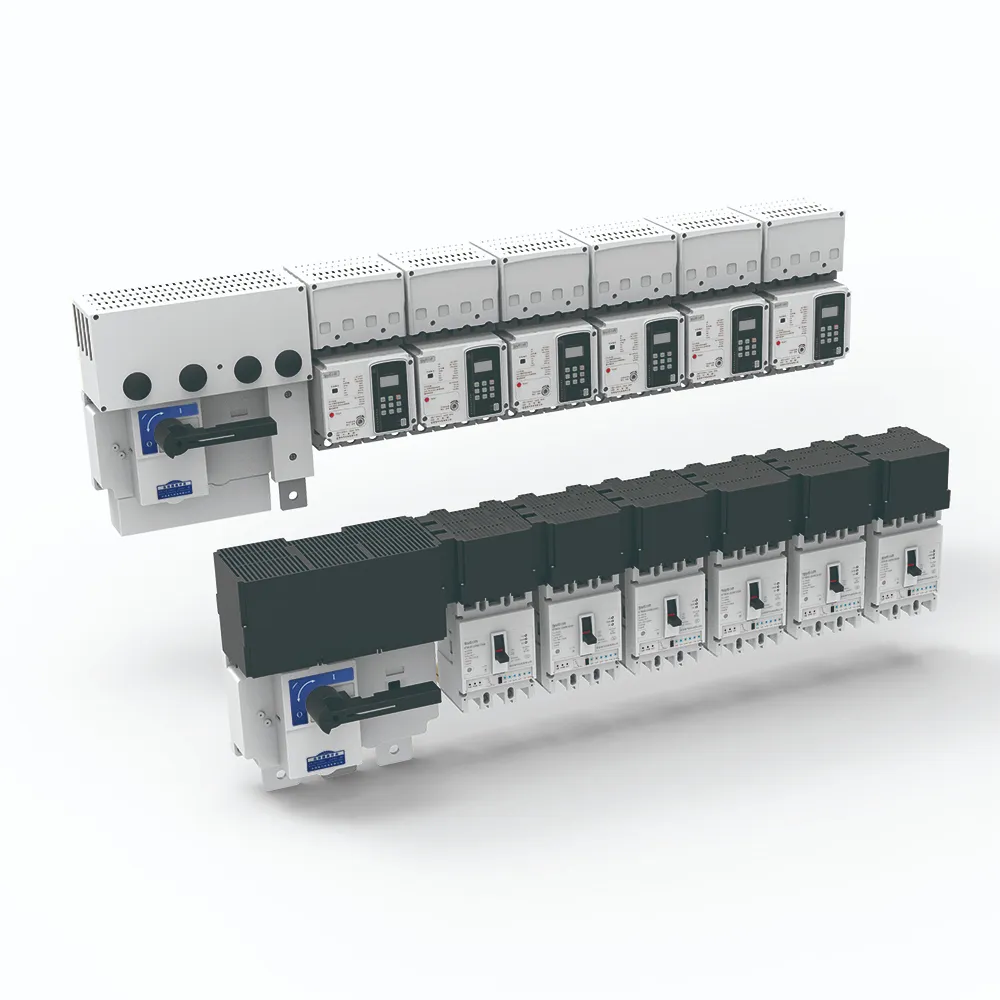
A busbar connection is the defined electrical and mechanical interface between two busbar sections, a tap-off unit, or a busbar system and a panel. The connection includes the conductor overlap or plug interface, joint hardware, enclosure transition, phase identification, and the installation sequence shown on the approved documents.
It is narrower than the complete busbar system. The LV busbar system guide explains system architecture; this article owns the interface decisions that let a panel shop release a layout and request a quotation. Keep the distribution box category as the upward product family reference when the connection feeds a distribution enclosure.
Part 2. Which dimensions belong in a busbar joint drawing?
Start the joint drawing with the connection datum, not with a generic busbar width. Record the system orientation, phase order, neutral or protective-conductor position, enclosure reference, and the direction from which the mating section approaches. Add the bolt or plug pattern, access side, bend-space envelope, and any removable cover needed for inspection.
The exact conductor size, current designation, joint hardware, and tightening method must come from the released ETFZX drawing or the selected manufacturer document. A generic table can organize a request, but it cannot invent dimensions.
| Drawing input | Why the panel shop needs it | Evidence to attach |
|---|---|---|
| Connection datum and orientation | fixes the mating direction and panel cut-out | GA or interface drawing |
| Phase, neutral and PE order | prevents a mirrored or incomplete termination | single-line and wiring diagram |
| Joint or tap-off type | fixes hardware, cover and access space | manufacturer assembly sheet |
| Enclosure transition | aligns gland plate, flange or adapter | panel GA and busbar section drawing |
| Inspection and service access | keeps covers removable after wiring | layout mark-up and maintenance note |
When a dimension is not released, mark it as “to be confirmed” in the RFQ. Do not fill the gap with a typical value from another busbar family.
Part 3. How is the enclosure and panel interface checked?
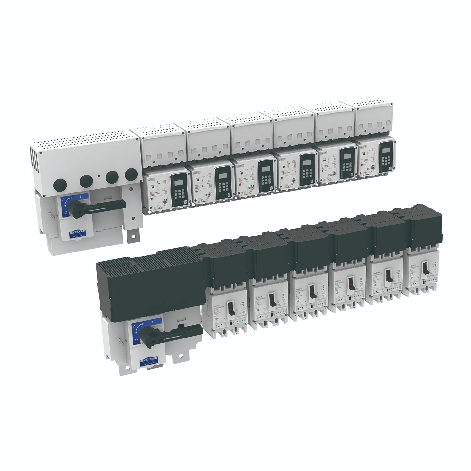
Check the enclosure boundary in three views: plan for alignment, elevation for support and access, and section for clearances and cable entry. Confirm that the panel wall, gland plate, flange, and busbar enclosure do not compete for the same space. Mark the support points and the route of the neutral and protective conductors on the same controlled revision.
The panel board guide covers the wider board layout. For a connection review, add the busbar manufacturer interface drawing, the panel GA, earthing arrangement, and the cable schedule. If a tap-off unit is used, reserve working space for its operating handle and for the test or inspection action required by the project.
Part 4. What should be verified before energizing a connection?
Verification starts with identity. Compare the installed section, joint kit, labels, phase sequence, and enclosure marking with the approved revision. Confirm that covers, barriers, supports, and access panels are fitted as shown; a connection that is electrically continuous but cannot be inspected is not a complete handover.
Then follow the authorized project procedure for continuity, insulation, torque evidence, and functional checks. The responsible design authority decides which tests apply to the assembly and records the acceptance criteria. Keep the test sheet, red-line drawing, and any nonconformance disposition with the panel dossier.
Important: Do not infer a short-circuit value or a torque setting from a product photograph. IEC 61439-1 and the manufacturer’s assembly instructions define the evidence needed for the completed interface; escalate missing data before energization.
Part 5. What should a busbar connection RFQ include?
Send with the inquiry:
| RFQ input | Purpose |
|---|---|
| System family and connection role | identifies joint, tap-off or panel transition |
| Released GA and interface drawing | fixes orientation, datum and cut-out |
| Rated voltage, current and frequency | sets the declared application envelope |
| Phase, neutral and PE arrangement | prevents an incompatible conductor order |
| Enclosure dimensions and entry direction | checks physical fit and service access |
| Joint hardware and cover requirements | defines the bill of materials |
| Quantity, accessories and delivery point | makes the quotation comparable |
| Required inspection and test records | aligns the handover dossier |
Include photos only as orientation aids; the controlled drawing remains the governing input. Keep one revision number on the drawing, schedule, and inquiry so that a later clarification does not silently change the joint.
Part 6. When is ETFZX a sensible product route?
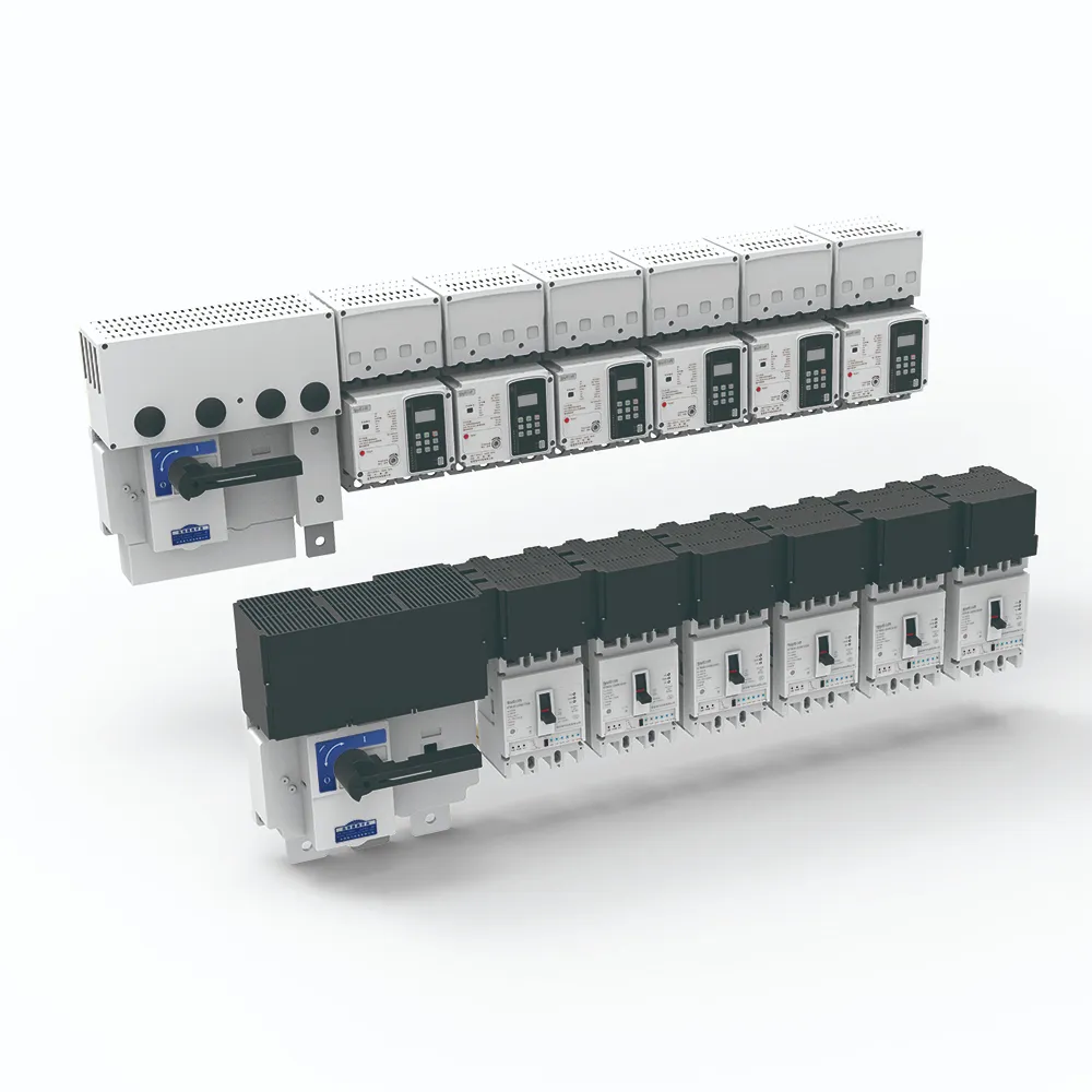
ETFZX is a sensible SUTON product route when the project needs an enclosed low-voltage busbar family and the panel team can supply the interface drawing, enclosure boundary, conductor arrangement, and inspection requirements for review. The ETFZX enclosed busbar system page is the correct first-party starting point for a family-level inquiry.
The public product page does not establish a universal joint dimension, current, short-circuit withstand, certification, or panel fit. Those claims remain model- and project-specific. If the interface is still undefined, do not recommend a final kit; send the GA, single-line, schedule, and access constraints through Contact SUTON for a documented review.
FAQ
What is a busbar connection?
It is the electrical and mechanical interface joining busbar sections, a tap-off, or a busbar system to a panel, including the joint, enclosure transition, identification, and installation evidence.
Which dimensions belong in a busbar joint drawing?
Record the datum, orientation, phase and neutral order, joint pattern, access side, bend-space envelope, cover, and enclosure transition. Use the released manufacturer drawing for exact dimensions.
How is a tap-off or panel interface specified?
Specify the tap-off or transition role, mating direction, conductor order, enclosure cut-out, operating access, and the drawing revision that governs the assembly.
What enclosure and neutral details must be checked?
Check the panel wall, flange or gland plate, support points, cable entry, neutral route, protective-conductor route, and service clearance in plan, elevation, and section views.
What should be verified before energizing a connection?
Verify identity, labels, phase sequence, covers, barriers, supports, continuity, insulation, torque evidence, and the authorized project test record against the approved revision.
What should a busbar connection RFQ include?
Send the family, connection role, GA and interface drawing, declared electrical inputs, conductor order, enclosure boundary, hardware, quantities, accessories, and required inspection records.
When is ETFZX a sensible product route?
Use ETFZX as a family-level inquiry route when an enclosed LV busbar interface is required and the project can provide controlled drawings and assembly inputs; confirm exact fit and ratings with SUTON.