


Specify a panel board as coordinated sections with a named assembly verifier — not as a pile of parts that nobody owns.
Commercial and light-industrial buyers use the term when they need a populated distribution assembly: incomer section, busbar and device sections, section coordination, assembly responsibility, and a conscious factory-versus-site population decision. Start from the single-line diagram and feeder schedule, then compare quotations against the same controlled documents.
Important: This guide structures panel-board section planning for LV assemblies in line with integration practice in IEC 61439-1 and device duties in IEC 60947-2. It cannot approve section ratings, coordination results, or verification coverage where supply data, fault duty, or device schedules are missing — hold those inputs for engineering review before procurement.

Part 1. Turn a panel board request into documented section inputs
In commercial and light-industrial projects, a panel board is the populated distribution assembly that takes one incoming feed and distributes it through feeder and final-circuit devices. Regional vocabulary blurs the term with switchboard and distribution board; the practical boundary is scale and role. Definitions for the panel as such live in the circuit breaker panel guide; board sizing basics live in the distribution board sizing guide.
The table below maps a panel-board request into section-level inputs that quotations can answer consistently.
| Selection factor | Why it matters for the panel board | Send with quote |
|---|---|---|
| Single-line diagram and supply data | fixes incomer scope and earthing context | yes |
| Prospective fault level at the board | fixes ratings and withstand duty | yes |
| Feeder schedule with downstream loads | fixes feeder sections and device list | yes |
| Final-circuit schedule and residual plan | fixes modular sections and ways | yes |
| Coordination and selectivity expectations | demands evidence per device pairing | yes |
| Busbar continuous current and tap-off needs | fixes bar sizing and section geometry | yes |
| Population mode (factory or site) | fixes assembly and logistics scope | yes |
| Verification evidence and record format | fixes compliance ownership | yes |
| Enclosure environment and access | fixes thermal and maintenance constraints | yes |
| Standards requested and quantity | fixes approval scope and procurement batch | yes |
Projects that skip the table often receive quotations built on a device count alone. That produces a second procurement cycle once coordination, verification ownership, or population mode is challenged on site.
Part 2. Map the section anatomy of a populated board
Sections are the planning unit. Specify each one explicitly and the board stops being a guess.
| Section | Contents | Key inputs |
|---|---|---|
| Incomer section | main device, metering, isolation | supply data, fault level, isolation needs |
| Busbar system | bars, supports, connections | continuous current, fault withstand |
| Feeder section | molded-case devices for sub-boards | feeder schedule, selectivity plan |
| Final-circuit section | modular devices on DIN rail | circuit schedule, residual plan |
| Auxiliary section | controls, signaling, surge devices | control philosophy, SPD decision |
The section table also keeps later modifications honest: a change lands in a named section with its own inputs, instead of somewhere in a crowded enclosure. Busbar-system selection detail lives in the live busbar system guide once this article establishes section boundaries.
Part 3. Collect incomer and feeder inputs from supply and schedule data
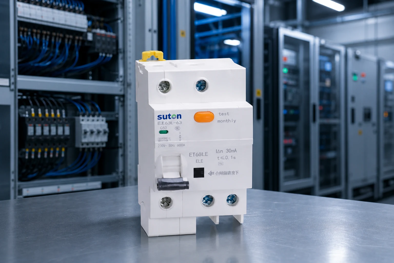
Collect supply characteristics first: voltage, frequency, phase and neutral arrangement, earthing system, prospective fault current at the board, and the upstream protective device. The incomer section, main device duty, and isolation arrangement follow from these, with role detail covered in the main switch selection guide.
Feeder inputs come from the downstream world: each sub-board or load center’s demand, cable route and length, and required protection duty. Write them as a feeder schedule, because that schedule becomes both the device list and the busbar loading evidence.
Confirm module positions, terminal orientation, bending space, and door clearance on the schematic while the interior layout is still open to change.
A device that meets electrical ratings but cannot be wired, adjusted, or tested during commissioning creates a compliance gap that appears only at handover.
Part 4. Coordinate device sections and thermal behavior
Coordination turns sections into one system. Feeder devices must clear faults without dragging the incomer out; final-circuit devices must trip before feeders; residual protection must discriminate by sensitivity or time where devices sit in series. The evidence is data — manufacturer selectivity tables, energy-limitation data, and the project fault study — assembled per pairing.
Thermal coordination is quieter but just as binding. Device heat output, enclosure size, and ambient temperature interact; a full board in a warm plant room may need derating decisions recorded at design time, not discovered as nuisance trips in the first summer. Coordination evidence must come from manufacturer selectivity tables and the project fault study for each pairing — not from matching nominal currents on unrelated datasheets.
Part 5. Assign assembly verification ownership and population mode
An assembly is verified as a whole under the applicable framework — clearances, temperature behavior, mechanical operation, and markings belong to the completed board, not to individual devices. Whoever builds the board owns producing that evidence, and whoever modifies it inherits the duty for the change.
Factory population buys documented assembly conditions and testing before dispatch; site population buys flexibility on late changes and access constraints. Either can be right — the RFQ must state which is priced. Contracts should name the verifier before parts are bought. A project that buys interiors, enclosures, and devices separately without naming the verifier has quietly assigned assembly risk to whoever touches the board last.
Review spare strategy per section rather than per board. Feeder sections may justify equipped spares ready for cable, while final-circuit sections may only need blank ways and cover space. Note who supplies blanking and labeling material with the order.
Part 6. Route an evidence-based SUTON inquiry
Send with the inquiry:
- approved single-line diagram and supply data with prospective fault level
- feeder and final-circuit schedules with coordination expectations
- busbar continuous current needs and tap-off positions
- population mode (factory or site) and verification evidence requirements
- enclosure environment, access constraints, and mounting interface
- standards requested, labeling expectations, and quantity
Require suppliers to declare the exact offered section configuration, device markings, assembly scope, accessories, and any exceptions against the controlled documents. Hold the engineering decision when fault duty or coordination evidence is incomplete — a quotation against undefined supply data cannot preserve the design intent.
Fit Boundary: this guide plans board sections and responsibilities for LV projects. It does not perform fault studies, does not verify assemblies, and cannot allocate verification duty where contracts are silent. Escalate those gaps to the design authority before the package is priced.

As a product recommendation starting point for populating sections: SUTON’s molded case circuit breakers category covers feeder-section candidates such as the ETM1 series molded case circuit breaker route, and final-circuit sections draw on modular DIN rail products. These are category routes; no section rating or verification coverage is established by a catalogue page.
Once the single-line diagram and schedules are approved, send the controlled documents through Contact SUTON for a documented review. Public pages do not fix section ratings, coordination, or assembly exceptions for a specific panel — those remain project-specific confirmations.
Section-plan review before ordering
Walk the single-line diagram against the section table once more before purchase. Every downstream board should have a feeder row, every feeder row a device, every device a position, and every position a labeled way in the interior drawing. Gaps found on paper cost minutes; gaps found at installation cost days.
File the whole decision trail — schedules, coordination data, verification ownership, population mode — in the panel dossier. That file is what turns the next extension, audit, or fault investigation into a reading exercise instead of an archaeology project.
When the panel is modified, update the schematic and schedule before energizing new circuits. An added feeder, changed coordination pairing, or swapped device alters verification scope even when nominal ratings appear unchanged.
FAQ
What is a panel board?
It is the populated LV distribution assembly that takes one incoming feed and distributes it through feeder and final-circuit devices, specified as coordinated sections.
What is the difference between a panel board and a switchboard?
Scale and role: switchboards sit closer to the supply with larger ratings, while panel boards distribute to downstream zones; regional vocabulary varies, so define terms in the project.
What sections make up a panel board?
Incomer, busbar system, feeder devices, final-circuit devices, and auxiliary equipment — each with its own inputs and drawing presence.
Who is responsible for panel board assembly verification?
Whoever builds the assembly owns the verification evidence, and whoever modifies it inherits the duty for the change; contracts should name this owner explicitly.
Should a panel board be factory-assembled or site-assembled?
Factory population brings documented assembly and testing before dispatch; site population brings flexibility under late changes — the RFQ must state which is being priced.
What data belongs in a panel board RFQ?
Provide the single-line diagram, supply and fault data, feeder and final-circuit schedules, coordination expectations, population mode, verification requirements, standards, and quantity — the Part 1 table lists what to send with a quote.