A voltage protector for compressor loads should be selected as part of the refrigeration or air-conditioning system's complete electrical and control design. Verify the supply configuration, monitored voltage conditions, switching duty and recovery sequence against the exact equipment instructions. Sustained overvoltage and undervoltage supervision does not replace short-circuit protection, motor overload protection, surge protection or the compressor controller's restart restrictions. Do not select a protector only from compressor power or a large current printed on its enclosure. The relevant question is whether the documented device and control arrangement meet the actual load's requirements.
Identify which compressor system is being protected
Start with the equipment identification, compressor model, supply diagram and controller manual. A small fixed-speed unit, a three-phase condensing unit and an inverter-driven system can have different incoming supply requirements and restart behavior. Identify whether the proposed protector carries the load directly or supervises a control circuit. The same word compressor can describe applications with very different electrical interfaces, so a product recommendation needs the exact equipment information.
Record the supply configuration and the equipment's permitted operating conditions from its documentation. Do not substitute the building's nominal voltage for the equipment's complete supply requirements. Identify the voltage conditions that the existing controller already detects and how it handles a disturbance. An external device should complement this sequence. It should not bypass controller faults, eliminate a required acknowledgement or interrupt the equipment in a way the manufacturer has not approved.
Distinguish the protection functions
A sustained-voltage protector supervises declared voltage conditions and acts through its documented output. A surge protective device addresses transient events within its own specification. A motor overload function and short-circuit protection have different purposes. A compressor controller can add operating and restart restrictions associated with the refrigeration system. Treat these as separate design items, even when a commercial product combines some of them in one housing.
Search results often group surge protection, voltage cutoff and compressor overload products together. That grouping is not evidence that the products are interchangeable. A quotation should identify each required function and the device responsible for it. If a proposed protector does not provide a function, retain the appropriate separate equipment. A larger current rating does not turn an overvoltage cutoff device into a complete motor-protection system or establish transient protection.
Review direct switching and contactor control
If the protector switches compressor supply directly, request explicit evidence for the applicable load duty, including the equipment's starting characteristics and the documented switching arrangement. Continuous current and starting behavior are different considerations. A protector that matches ordinary operating current may still be unsuitable for the proposed switching duty. Do not invent a multiplier to convert compressor power into a universal protector size.
Where a monitor operates a contactor, evaluate both devices and their connection as a system. Confirm the monitor output's control duty, the contactor's load duty, control supply behavior and the controller's interlocks. A relay output used for a contactor coil should not be compared directly with a device carrying compressor current. The final enquiry needs to state which arrangement is intended so the supplier can provide relevant evidence rather than a misleading headline rating.
Preserve the equipment's restart restrictions
Compressor equipment may require controlled restart after shutdown or a supply disturbance. The exact controller documentation determines the applicable sequence. A voltage protector's recovery timer may begin when its monitored voltage becomes acceptable, while the equipment's minimum off-time logic may reference the actual compressor stop. Those clocks can have different start events. Confirm their interaction before treating one as a replacement for the other.
Short repeated interruptions deserve particular attention. Ask whether the equipment retains its restart inhibition after loss of control power and whether the external protector begins a new recovery qualification. The desired behavior should be documented before testing. Do not repeatedly cycle an operating compressor to experiment with its restart behavior. Use a qualified commissioning method that follows the equipment instructions and preserves existing protective controls.
The US Department of Energy motor-systems resources provide general background for evaluating motor-driven equipment and its supply. They are not a model-specific compressor setting sheet. For a procurement decision, use the compressor and controller manuals as the controlling evidence for operating limits and restart restrictions. Keep a record of the exact documents reviewed so future replacement equipment can be assessed consistently.

Use an application review table
| Application item | Evidence required | Unsupported shortcut |
|---|---|---|
| Equipment identity | Compressor and controller manuals | Generic compressor label |
| Output duty | Documented direct switching or contactor arrangement | Continuous current alone |
| Restart | Controller off-time and recovery logic | Unlabelled delay value |
| Three-phase functions | Explicit phase supervision requirements | Three-phase name alone |
| Commissioning | Approved event, endpoint and acceptance method | Repeated live power cycling |
The table is a procurement and commissioning checklist. It intentionally avoids universal voltage thresholds, delay values and current multipliers. Those numbers need a defined equipment model, an installation requirement and supporting documentation. Ask the supplier to explain which evidence supports each proposed setting or rating. An unresolved entry should become a design question before purchase, rather than an assumption made during installation.
Separate normal operating observations from proof of protective capability. A unit running on one day at an acceptable supply does not establish how the system responds to an abnormal voltage condition or whether its output is suitable for repeated switching. Record the conditions covered by the equipment instructions and the controlled acceptance plan. Keep untested or undocumented conditions explicit in the handover record.
Review three-phase and inverter equipment separately
For a three-phase compressor system, determine whether the equipment requires phase-loss, phase-sequence or imbalance supervision in addition to voltage thresholds. These are separate functions and must be confirmed individually. A device described as three phase should not be assumed to include all of them. Check how the complete system prevents unsuitable operation and which control removes the load when a required supply condition is absent.
For inverter-driven equipment, follow the manufacturer's approved incoming supply and switching arrangements. The drive may have its own supervision, fault memory and restart configuration. An external protector should not be inserted into an arbitrary location based on a generic wiring sketch. Ask the equipment supplier whether the proposed arrangement is supported and what sequence is required after the protector restores supply. Avoid treating an inverter unit as an ordinary directly switched motor.
Account for refrigeration continuity and alarms
Electrical protection can interrupt cooling, so the system should make its state understandable. Determine whether the refrigeration controller, alarm system or operator receives a meaningful indication after a trip. A dark display can result from missing control power rather than a compressor fault. Record which indications remain available while the protector output is open and how the responsible team recognizes an unresolved interruption.
For temperature-sensitive operations, review continuity and escalation through the site's operating procedures. A voltage protector does not monitor stored-product temperature merely because it supplies refrigeration equipment. The appropriate alarm and contingency arrangements remain separate. Do not defeat voltage protection to restore cooling without resolving the cause and checking the equipment's instructions. A clear escalation path is more useful than repeatedly restarting a system with an unknown supply problem.
Review the actual SUTON reference product
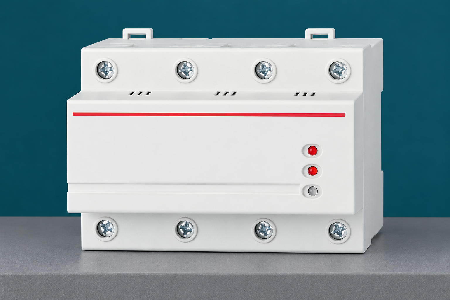
The SUTON DZ47-125V1 automatic-reset overvoltage and undervoltage protector is a relevant product family for a documented application review. The reference illustration shows its exterior. It does not prove a compressor switching duty, a particular restart timer or compatibility with every refrigeration system. Request the exact variant's current instructions and written confirmation against the equipment information before selecting it.
For a functional overview, see the automatic-reset voltage protector guide. Use the reconnection-delay review to separate supply recovery from equipment restart, and the single-phase versus three-phase selection guide to define sensing and switching requirements. These articles help structure a purchasing enquiry; they do not establish an undocumented product approval.
Commission through a controlled procedure
The acceptance plan should identify the protector, compressor equipment, controller, contactor if present and the relevant observation points. State the expected response to each approved simulated event. Record both output restoration and the equipment's subsequent behavior. If the equipment remains inhibited after supply returns, identify whether its own controller is correctly enforcing a restart restriction rather than assuming the voltage protector has failed.
The HSE guidance on electrical equipment work provides general context for planning the electrical part of this work. Qualified personnel should follow the installation's approved procedure and the exact equipment instructions. Do not open energized enclosures, bridge controls or create uncontrolled voltage disturbances on occupied equipment to prove a proposed setting. A safe test method and a defined acceptance criterion belong in the plan before any test begins.
Keep maintenance isolation independent
An automatic-reset device can restore its output after the monitored condition recovers. It must not be treated as a maintenance lockout or proof that compressor equipment is safe to work on. Other supplies or stored energy can also matter within the equipment. Use the complete equipment isolation procedure with competent personnel. A stopped compressor, inactive display or open protector output is not a substitute for that procedure.
The HSE safe electrical working practices publication provides broader guidance for establishing safe electrical work conditions. Apply it together with the equipment and site requirements rather than turning this article into a maintenance instruction. Preserve the distinction between operational protection and the controls used for servicing. That distinction remains necessary even when the protector normally disconnects supply automatically during a fault.
Prepare an enquiry that can be answered
Provide the compressor and equipment identifiers, current manuals, supply diagram, existing protection, starting information and desired recovery sequence. Describe whether the protector carries compressor current or operates a contactor control. Include the installation and environmental requirements adopted by the project. Request a clear statement of the supported application, applicable limits and any functions that require separate equipment.
At handover, retain the approved device identity, settings, connection information, test results and alarm interpretation. Assign responsibility for investigating recurring trips instead of normalizing them as routine behavior. When a compressor, controller or supply arrangement changes, review the protector application again. A replacement with similar power can still have different starting and recovery requirements, and the old selection should not transfer without checking.
Frequently asked questions
Can an automatic voltage protector replace a compressor overload device?
Not simply because it interrupts supply. Sustained-voltage supervision, overload protection and short-circuit protection have different functions. Confirm which functions the exact product provides and retain the equipment required by the compressor and installation design.
Is a large protector current rating enough for compressor selection?
No. Review the documented load and switching duty, starting behavior and whether the protector switches the compressor directly or controls a contactor. Match the complete arrangement to the exact equipment instructions and supplier evidence.
Can I shorten the recovery delay when cooling is urgently needed?
Do not change it merely to force a restart. Review the fault, supply condition and compressor-controller restrictions through the approved procedure. The required setting and restart sequence must remain consistent with the equipment documentation and site assessment.
Educational video
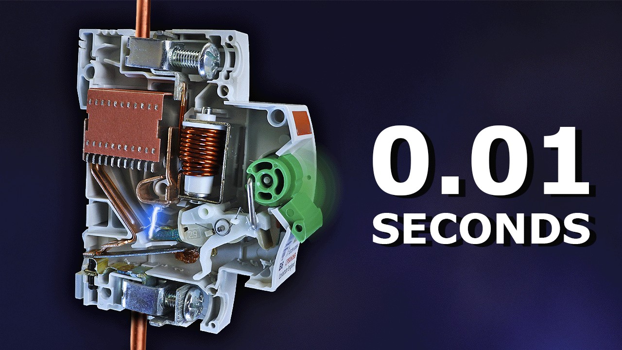
Why Circuit Breakers DON'T Protect People (electric shocks) by The Engineering Mindset. This video explains electrical-shock protection limits; it supports the safety-function distinction here, not an exact SUTON rating, protector response time, feed direction, fuse selection or maintenance procedure.