A transparent switch disconnector allows an operator to observe parts of the mechanism or contact state through a transparent cover or viewing feature. That visibility can help confirm product identity and interpret a local indication, but it does not prove that every conductor is de-energized. Selection still depends on the device's declared switching and isolation functions, its exact configuration and the completed panel. For procurement, distinguish a visible contact gap from a position flag, and distinguish both from voltage verification. This guide explains how to specify and review the SUTON HGL(ETGL)/TM transparent family without treating transparency as a universal safety approval.
Define what the viewing feature must show
A transparent enclosure, a small viewing window and a mechanical indicator are not identical features. A transparent component may reveal the mechanism while hiding part of a contact. A window may show one defined contact area. A colored flag may show a mechanism position rather than the actual separation of every pole. The purchasing requirement should identify what must be visible and from which operating position.
Ask the supplier to provide a drawing or a clearly identified photograph of the exact offered configuration. Mark the relevant viewing areas and the parts they reveal. If the project requires observation of all switched poles, confirm whether each pole can actually be seen after installation. Do not accept an attractive transparent product photograph as a substitute for this question. The final enclosure, door and barriers can change the available sight line substantially.
Separate observation from the isolation decision
Observation answers a limited question about something that can be seen. Isolation is a function established by the equipment design and the installed arrangement. Verification for work addresses whether the intended conductors are actually safe under the approved procedure. These are related layers of evidence, but none can simply replace the others.
For example, open main contacts do not necessarily remove an auxiliary supply, an alternate source or stored energy in connected equipment. A clear view of one switch says nothing about a separate backfeed path unless the electrical diagram establishes the relationship. Keep the source map and the work boundary beside the device information. The isolator switch planning guide covers that wider boundary; this article focuses on the limits and specification of the viewing feature.
Read the HGL(ETGL)/TM description as configuration evidence
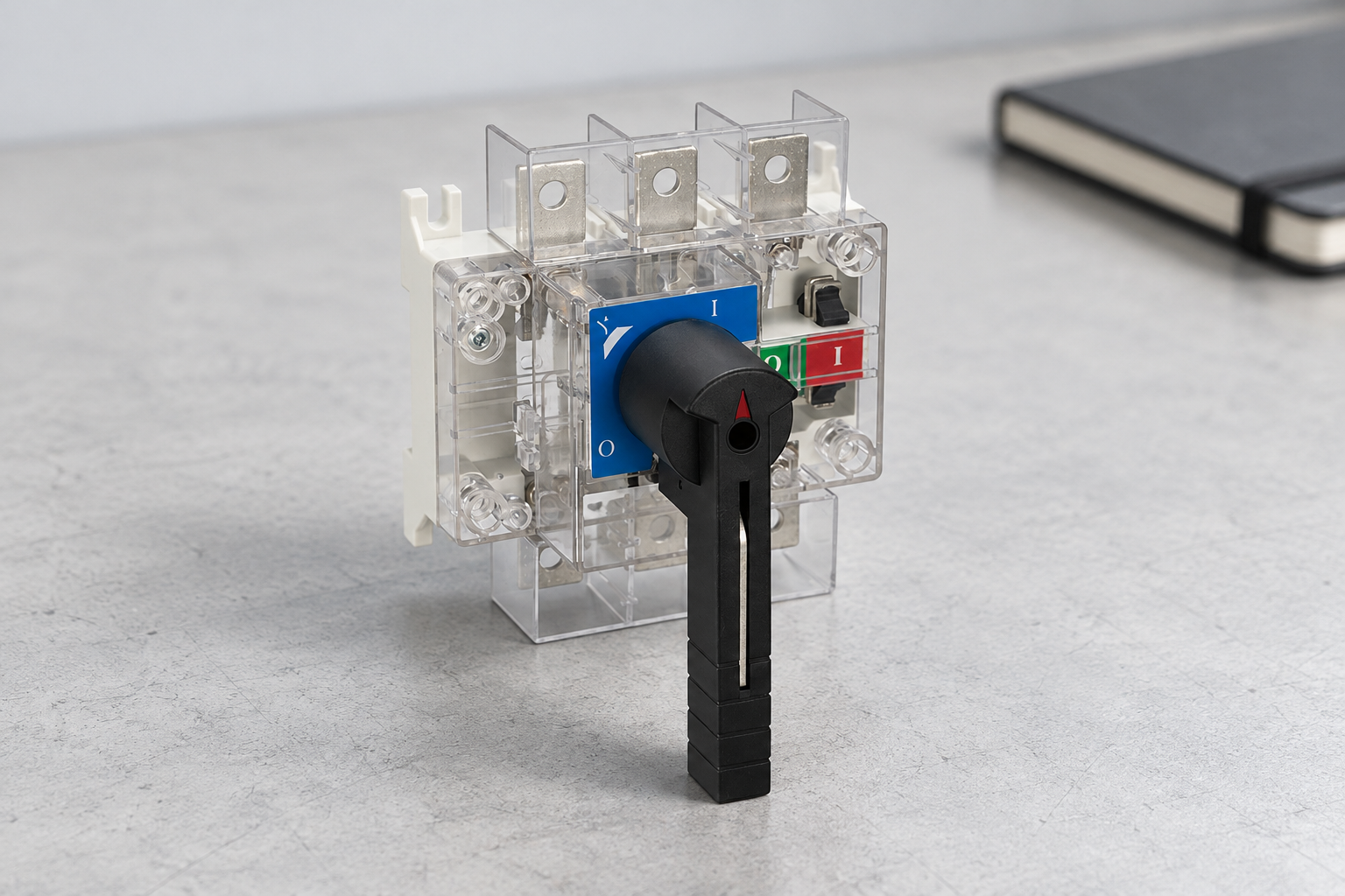
The SUTON HGL(ETGL)/TM transparent switch disconnector is described for alternating-current applications with direct or external cabinet operation. Its transparent top cover and smaller cover are intended to allow observation of the internal structure and contact open or closed status. The page describes three-pole and four-pole versions and an extended shaft for operation from outside the switchboard.
These statements identify a relevant family when visibility and operating access are important. They do not establish that every version satisfies a customer's particular visible-break requirement. Request the exact order code, pole arrangement, terminal drawing, installed viewing arrangement and applicable operating ratings. The phrase “transparent type” should appear in a specification only alongside the function it is intended to support.
The product page's stated voltage and current range also do not replace a configuration-specific review. Where a project has unusual load characteristics, environmental conditions or fault duty, obtain the supporting documentation for that application. Do not transfer ratings from a similar opaque family member solely because the exterior dimensions or handle look alike.
Use a viewing-feature review matrix
| Feature | Question | Evidence |
|---|---|---|
| Transparent cover | Which parts are directly visible? | Exact configuration image or drawing |
| Contact view | Can every required pole be observed? | Installed sight-line review |
| Position flag | What state does it represent? | Mechanism and indication description |
| External handle | Does the enclosure hide the view? | Complete operating arrangement |
| Environment | Will dirt or condensation obscure it? | Service conditions and maintenance instructions |
| Safe work | How is the work boundary verified? | Approved isolation procedure |
This qualitative matrix helps a buyer ask questions that a supplier can answer with a drawing, image or document. It is not a test method or a claim that all transparent products behave alike. Retain the answers with the approved panel layout. If the location of the viewing feature changes during a redesign, review the sight lines again rather than carrying forward an old acceptance mark.
The door-handle interlock guide addresses access and operation through an enclosure. It is complementary: a door interlock and a contact-viewing feature serve different purposes. Specify both individually where the project needs them.
Review the installed sight line before freezing the layout
Place the exact switch outline into the panel drawing with its operating shaft, handle, barriers and cable route. Identify where an authorized person can stand and what can be observed with doors and covers in their permitted positions. A feature that is visible on a bench can disappear behind a door flange or a cable bend in the finished assembly.
Consider lighting, reflections, label placement and the distance from the viewing area. Do not assume that a transparent cover remains useful when it faces a dark rear compartment. If an observation requires opening a door, document the access conditions and limitations. Avoid removing a protective cover merely to improve visibility; that changes the safety arrangement and requires engineering review, not a cosmetic adjustment.
Preserve the distinction between a flag and actual contacts
A position indicator can be valuable when its relationship to the switching mechanism is documented. However, procurement records should describe what the indicator represents rather than renaming it a visible contact gap. Ask whether a displayed state applies to the handle, mechanism, main contacts or a specific auxiliary contact. Different answers have different implications for inspection.
During acceptance, record the actual features observed and the corresponding documentation. An entry such as “all three required contact observation points visible from the approved access position” is more informative than “window passed.” If a pole cannot be seen, record that limitation and obtain a design decision. Do not infer its state from the appearance of a neighboring pole.
Account for contamination and cover condition
A transparent surface can become scratched, dirty or obscured. The maintenance plan should state how the manufacturer permits it to be inspected and cleaned, and what condition requires replacement or further review. Do not apply an arbitrary solvent or abrasive based on experience with a different plastic. Material compatibility belongs to the actual product instructions.
A viewing feature also does not establish the completed enclosure's ingress-protection rating or suitability for condensation and conductive dust. The environment around the contacts and insulation must remain within the declared conditions. Keep enclosure selection, equipment service conditions and the inspection method aligned. Where the project requires a particular IP rating, ask for evidence for the complete assembly rather than assigning a rating from the switch photograph.
Retain the electrical ratings independently of visibility
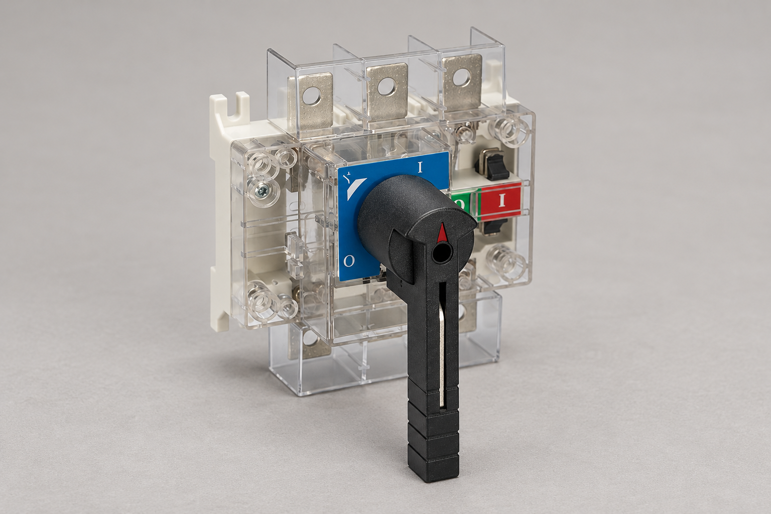
The visible mechanism cannot show whether the offered configuration has adequate voltage, utilization category, current duty or short-circuit performance. Those decisions require documentary evidence. Identify the exact load and operating frequency, the required isolation role and the upstream protective device. Compare each requirement with the manufacturer's declared conditions for the complete code.
The switch-disconnector making and breaking capacity guide explains why normal load switching and fault duties are different. A transparent cover provides a view; it does not turn an isolation-only configuration into a load-breaking device or an overcurrent protective device. Preserve those distinctions on the equipment schedule and during substitution review.
Keep the safe-work procedure separate and explicit
The HSE guidance on work near electricity identifies suitable isolation, control of reconnection and reliable confirmation that the intended circuit is no longer live as important checks. Its relevance here is the limit of visual information: seeing the switch does not establish every electrical condition in the work area.
The HSE guidance on working on electrical equipment provides further professional guidance, including consideration of additional supplies. Use it within the applicable rules and approved site procedure. This article does not give an operating sequence or authorize work on exposed conductors. The competent person must establish the appropriate method for the actual installation.
Prepare a precise transparent-switch inquiry
Send the supplier the switch location, pole arrangement, required operating duty, enclosure drawing and a description of what must be observed. Identify whether direct contact observation, a mechanical position indicator or both are required. State the permitted viewing position and whether the enclosure must remain closed during observation. Include the requested external handle and shaft arrangement where applicable.
At delivery, compare the offered code and accessories with the approved evidence. Check that labels, cable installation and barriers preserve the intended sight line. Record photographs under the permitted inspection conditions and retain the exact document revision. A change to enclosure depth or switch orientation can justify a fresh review even when the electrical ratings have not changed. This keeps the visibility requirement useful throughout the panel's service life rather than only during purchasing.
Frequently asked questions
Does a transparent cover prove that a circuit is dead?
No. It provides visual information about the parts that can be seen. Isolation from relevant sources and the required voltage verification remain separate responsibilities under the approved procedure.
Is a colored position flag the same as a visible contact gap?
No. Confirm what the flag represents and which contacts, if any, can be observed directly. Document the distinction in the specification and acceptance record.
Can an opaque model's ratings be assumed for a transparent version?
No. Verify the exact offered code, configuration, operating conditions and supporting documents. Similar appearance or family naming does not establish identical approval for the proposed duty.
Educational video
SELECT Safe Isolation Animation 2024 by SELECT. SELECT is the Scottish electrical trade association. This neutral training animation supports the safe-isolation discussion; it does not establish a SUTON-specific operating sequence or replace the approved site procedure.