


A single-pole breaker is the right choice only when one current path requires the device’s protection and switching function under the system design and applicable rules. “Single phase,” a familiar voltage, or a narrow module width does not prove that 1P is correct.
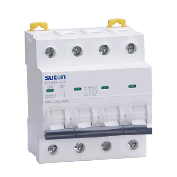
Panel builders should decide pole count from the conductors and required simultaneous operation, then select current, voltage, curve and breaking capacity. The modular DIN-rail range is the product pathway after that design decision.
What “single pole” actually describes
Pole count identifies how many current paths the device switches or protects as part of one mechanism. It does not describe the entire system, and it is not another name for ampere rating.
A 1P breaker may be available at many currents. Conversely, the same current rating may appear in 1P, 2P, 3P and 4P configurations. The project must therefore document both fields.
Decide from topology and simultaneous operation
| Design question | What to establish | Why it affects pole count |
|---|---|---|
| Which conductors carry load current? | actual circuit topology | identifies the paths involved in the circuit |
| Which conductors require overcurrent protection? | earthing/system and project rules | not every conductor is treated identically |
| Which conductors must open together? | isolation and fault-response requirement | may require a common multi-pole mechanism |
| Is the neutral switched or protected? | applicable rules and equipment design | cannot be assumed globally |
| What voltage exists across each pole and the device? | system voltage arrangement | each published rating must be respected |
| What load behavior is expected? | steady current and inrush | controls current and trip curve, not pole count alone |
| What is the prospective fault current? | short-circuit calculation | controls required breaking capacity |
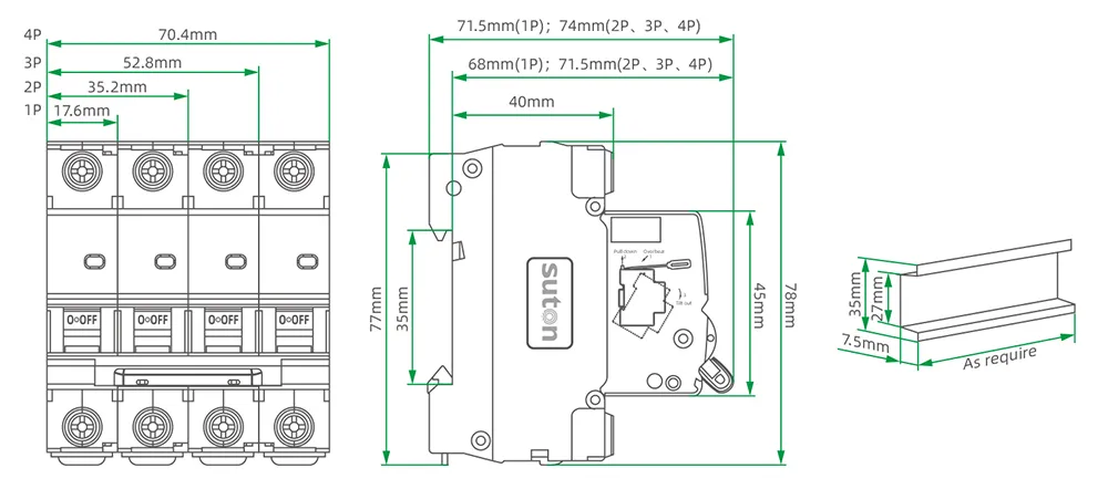
Two adjacent 1P breakers are not automatically one 2P breaker
Putting two independent single-pole devices beside each other does not automatically provide common operation, approved handle linkage, coordinated tripping or the isolation function required from a two-pole device. Use a verified multi-pole configuration when simultaneous behavior is required.
The live double-pole MCB guide covers 2P intent. Keep the single-pole page focused on circuits for which the design genuinely requires one pole.
Complete the MCB selection after pole count
Once 1P is confirmed, document:
- design current and load duty;
- protected conductor and installation conditions;
- rated voltage and frequency;
- trip curve or instantaneous response requirement;
- prospective fault current and breaking capacity;
- ambient, altitude and side-by-side installation;
- terminal, busbar and mounting interface;
- auxiliary/alarm/shunt requirements;
- applicable standard and approval evidence.
These fields prevent a correct pole choice from becoming an incomplete breaker specification.
Compare verified SUTON 1P product paths
The DZ47 Series MCB page publishes 1P–4P options across its family. The ETB-63 high-breaking MCB page lists 1P/2P for 230/400 V and 3P/4P for 400 V, with rated-current options through 63 A. For higher modular current requirements, the ETC65-125 Series page lists 1P–4P and 80 A, 100 A and 125 A options.
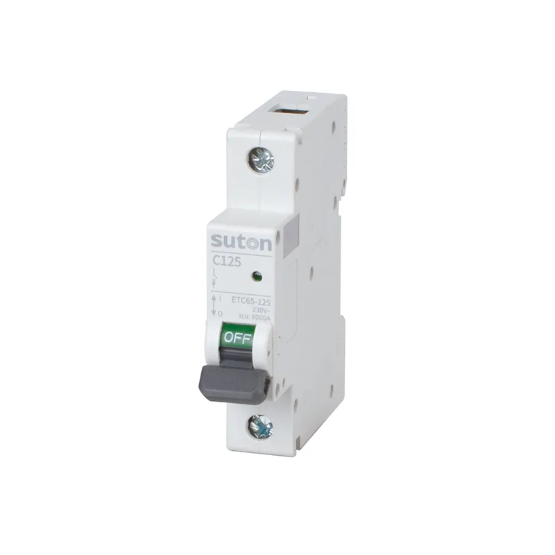
These are family-level paths, not interchangeable SKUs. Confirm the exact pole, voltage, current, curve, breaking capacity, dimensions and accessories before approving the BOM.