Busbar temperature rise is the increase in conductor or connection temperature above the relevant ambient reference under specified loading conditions. There is no single temperature-rise limit that can be safely applied to every LV busbar assembly. The acceptable result depends on the applicable assembly standard, conductor and connection materials, nearby insulation, connected equipment and verified operating conditions. For procurement, request the temperature-rise evidence for the complete supplied assembly. A generic current-density chart, a handheld temperature reading or the rating of an individual breaker cannot establish the thermal capability of an enclosed panel.
Distinguish temperature from temperature rise
Use the relationship ΔT = Tmeasured – Tambient, where both temperatures are taken using the defined test reference and conditions. A temperature difference can be expressed in kelvins or degrees Celsius with the same numerical value. For example, a hypothetical conductor at 70°C with a relevant ambient of 35°C has a 35 K rise. This arithmetic does not say that 70°C or 35 K is acceptable for the assembly.
A report needs to identify the measurement location and ambient reference. Outdoor air, room air and air trapped near the upper part of a panel can have different temperatures. Comparing a joint temperature with a remote weather reading may therefore create an unhelpful result. For acceptance, use the measurement arrangement and criteria required by the applicable verification method.
Absolute temperature remains important because insulation, terminals and adjacent equipment have their own service limits. A moderate rise in a hot room can still produce an unsuitable final temperature. Conversely, a cool-room observation does not prove the same assembly will perform adequately at the project's maximum ambient. Record the operating range and any declared restrictions before comparing proposals.
Understand where the heat comes from
For a simple resistive approximation, electrical loss is P = I²R, with current in amperes, resistance in ohms and loss in watts. If a hypothetical path has 100 micro-ohms resistance and carries 400 A, the calculated loss is 16 W. At 600 A with resistance held constant, it becomes 36 W. The example shows the strong effect of loading; it is not a prediction of any SUTON assembly's temperature.
NIST's definition of the joule connects electrical current, resistance and heat. In a real AC busbar, effective resistance and heat removal also depend on frequency, conductor geometry, operating temperature, surrounding conductors and the enclosure. A loss calculation is therefore one input to thermal assessment, not a complete temperature-rise calculation.
Include joints and terminal interfaces in the loss review. A local connection can run hotter than the adjacent straight bar because its interface condition and geometry differ. Nearby breakers and other components also contribute heat. Evaluating only the main bar can miss a limiting outgoing terminal or a hot region near closely packed equipment.
Read the assembly verification requirements correctly
IEC 61439-1 establishes general requirements and verification principles for low-voltage assemblies and is used with the relevant assembly-specific part. Its public description highlights group rated current and temperature-rise verification. This makes the simultaneous loading of circuits a relevant procurement question, rather than simply adding the catalog ratings of every outgoing breaker.
Ask which verification route applies to the proposed construction and how the evidence covers the offered design. A test report from another enclosure or a different outgoing arrangement needs an explained relationship to the supplied assembly. Changes to ventilation, partitions, device quantity or connection layout can affect that relationship. A document bearing a familiar standard number is not enough without configuration identity.
Avoid copying a temperature-rise number from a search snippet into the specification. Different parts and materials can have different criteria, and the controlling requirement may involve both temperature rise and permissible operating temperature. The design authority should establish the applicable limits from the project standard and equipment requirements, with the manufacturer stating how those limits are met.
Define the loading case before comparing results
A meaningful thermal submission states the incoming current and the simultaneously loaded outgoing circuits. Include the intended load diversity, operating duration, conductor connections and installation conditions. If one proposal assumes fewer heavily loaded outgoing circuits than another, their headline current values may not be directly comparable. Resolve the assumptions before negotiating on nominal amperes.
Consider nonlinear loads and the neutral path when relevant. A neutral carrying harmonic current contributes heat inside the enclosure even when the fundamental phase currents appear balanced. Use the neutral busbar sizing guide to define that duty separately. Do not assume a phase-current thermal test automatically represents every possible neutral loading condition.
For continuous production, distinguish sustained operation from a short demonstration. Record the thermal stabilization or assessment criteria used by the selected method. A panel that remains cool during a brief factory demonstration has not necessarily reached the condition represented by its declared rating. Ask for the complete record rather than a photograph of a meter display.
| Review item | Record needed | Question to resolve |
|---|---|---|
| Acceptance criteria | Applicable standard and equipment limits | Which parts and temperatures control acceptance? |
| Loading | Incoming and simultaneous outgoing currents | Does the test or calculation cover project duty? |
| Ambient | Declared range and measurement reference | Does the evidence cover the installation? |
| Enclosure | Dimensions, partitions and cooling arrangement | Does the supplied configuration match? |
| Connections | Joint and terminal construction | Are interface losses and limits covered? |
| Modifications | Device, ventilation or layout changes | Is reassessment required? |
This checklist identifies evidence to compare; it deliberately does not reproduce a universal limit table. The acceptance values and verification method must come from the applicable requirements and the identified assembly design. Keep the agreed thermal submission with the purchase order and final documentation so later changes can be assessed against the same baseline.
Check the enclosure and the installation environment
Heat must leave the assembly through its surfaces and any intended ventilation paths. Enclosure dimensions, mounting arrangement, compartmentation, installation clearances and ambient conditions influence that process. An assembly verified in one arrangement may require additional assessment when installed against other equipment, inside a secondary cabinet or near an external heat source.
Do not add fans or remove covers as an informal solution to excessive temperature. These changes can affect protection against contact, ingress protection, contamination and the validity of the thermal evidence. A forced-ventilation design also needs its intended maintenance and failure response considered. Any modification should follow an approved revised design and matching verification.
Where calculation is used, request the method, input losses and applicability checks. The IEC TR 60890:2022 publication concerns temperature-rise verification by calculation. A reference to a calculation method does not mean it applies without restrictions to every enclosure or that it replaces all relevant assembly requirements. The responsible engineer must establish the correct scope and edition for the project.
Investigate a hot joint without creating another fault
A maintenance observation should first establish the operating conditions and measurement quality. Compare equivalent joints under comparable loading, note surface finish and emissivity, and record ambient conditions. Reflective metal can make infrared readings difficult to interpret. A hot-looking image is evidence to investigate, not a reliable instruction to tighten a particular connection.
Any inspection requiring access to conductors needs the site's safe working procedure and qualified personnel. Do not recommend live retightening or an invented torque correction. After appropriate isolation, inspect according to the manufacturer instructions for damage, incompatible interfaces, incorrect assembly or contamination. Replace damaged parts where the approved procedure requires it rather than concealing a problem with a higher tightening force.
Close the investigation with a comparable verification record. Record the identified cause, approved corrective work, final assembly condition and subsequent measurement conditions. If the issue arose from an operating duty outside the original specification, correcting a joint alone may not solve it. Reassess the load or assembly design instead of repeatedly repairing the same symptom.
Review the actual SUTON product documentation
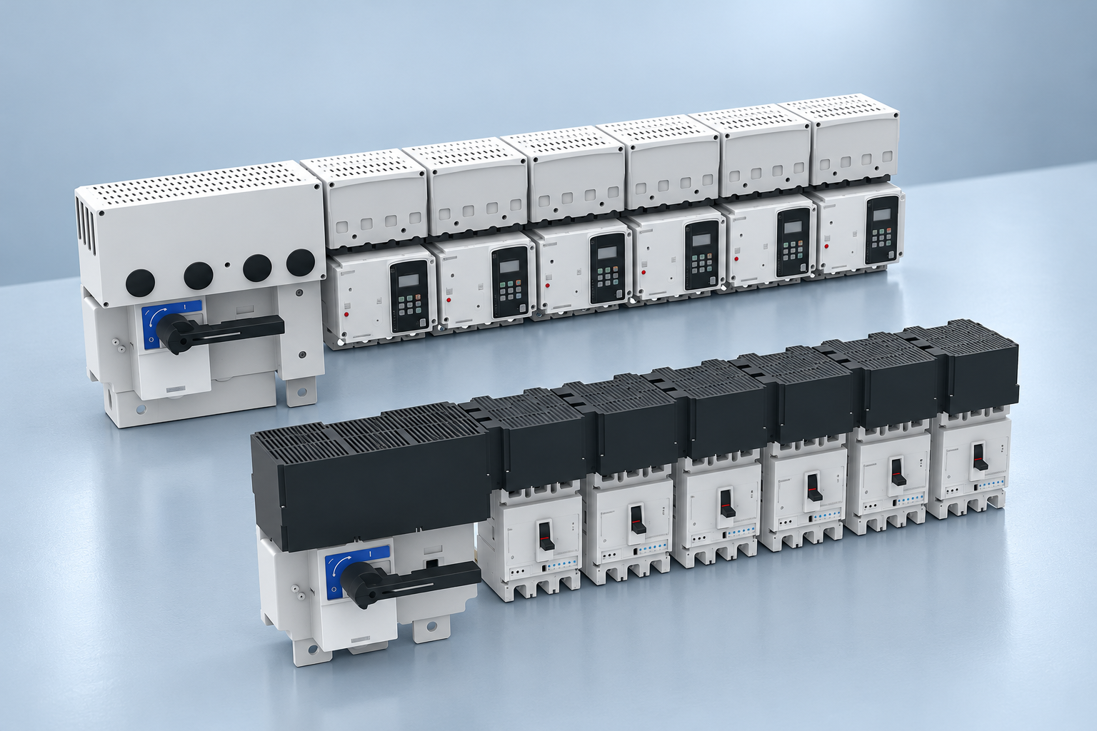
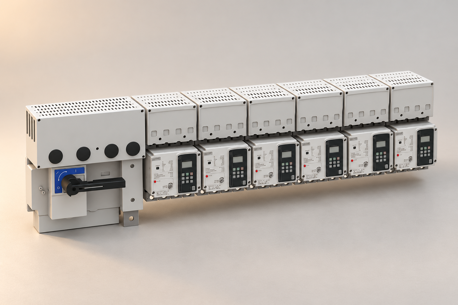
Use the SUTON ETFZX enclosed busbar system as the starting point for an order-specific discussion. The illustrations here are exterior references, not thermal images or evidence of internal temperature. They do not prove a conductor material, a permitted temperature rise or the result of an assembly test.
Provide SUTON with the circuit schedule, simultaneous phase and neutral currents, enclosure and installation environment, operating duration and required project standard. Request the applicable construction drawing, declared characteristics and verification evidence. If the proposed arrangement changes during quotation, update the document list and confirm that the supporting evidence still matches.
Coordinate the thermal decision with the busbar system overview for panel builders, current rating calculation and short-circuit withstand guide. Adequate thermal performance does not establish fault withstand or insulation spacing, and those requirements should be checked on the same final design.
Frequently asked questions
Is there one temperature-rise limit for every busbar?
No. The applicable criteria depend on the assembly standard, construction, conductor and connection materials, insulation and connected equipment. Obtain the limits and matching verification for the actual design instead of applying a single number from a generic chart.
Can a thermal camera prove the assembly current rating?
No. Thermography can support condition assessment, but its result depends on loading, emissivity, access and ambient conditions. A field image does not replace the required design verification or prove operation at the declared maximum duty.
Does increasing busbar cross-section always fix overheating?
No. The limiting issue may be a joint, terminal, surrounding equipment, ventilation or an operating condition outside the design. Identify the cause and verify the revised complete assembly rather than changing conductor area alone.
Educational video
Ohms Law Explained – The basics circuit theory by The Engineering Mindset. This educational video explains current, resistance and Ohm's law as background for conductor losses. It does not provide a temperature-rise limit or verify an assembly rating.