


Reverse feed MCCB use is acceptable only when the manufacturer documentation and applicable approval for the exact model permit power to enter the terminals normally treated as the load side. Do not decide from the molded case or symmetrical-looking terminals. Verify line/load markings, trip-unit power supply, voltage sensing, earth-fault sensing, accessories, isolation duty, breaking capacity, installation orientation and any restrictions in the certificate or instructions. If the device is marked for one direction or the evidence is silent, treat reverse feeding as unapproved until the manufacturer confirms it in writing.
What reverse feeding means
In a conventional arrangement, supply conductors connect to the designated line terminals and the protected circuit connects to the load terminals. Reverse feeding swaps that power-flow direction. It may arise in generator, photovoltaic, energy-storage, bus-tie, transfer or backfeed applications. It is not the same as reverse current: AC power direction can change while current still alternates, and a breaker may be required to interrupt fault current from either side.
Some thermal-magnetic devices are mechanically symmetrical; others contain electronic trip units, control-power circuits, voltage sensors or accessories that are not. A correct decision therefore depends on the exact catalog number and configuration. Never generalize from a different frame in the same family.
| Verification item | Why reverse feed can matter | Acceptable evidence |
|---|---|---|
| Line/load marking | May establish mandatory connection direction | Exact instruction sheet and device marking |
| Trip-unit power and sensing | Electronic functions may expect a defined source side | Trip-unit manual and wiring diagram |
| Breaking capacity | Fault source can be present on the opposite terminals | Declared rating at actual voltage and orientation |
| Earth-fault function | Sensing and neutral treatment can be directional or position-dependent | Protection manual and approved study |
| Accessories | Shunt trip, undervoltage release and indication may have restrictions | Accessory wiring and compatibility table |
| Isolation and exposed parts | Both sides may remain energized from different sources | Single-line, lockout procedure and labeling plan |

Read markings and instructions literally
Inspect the breaker for LINE, LOAD, source arrows, polarity, terminal numbers and warnings. Then compare those markings with the current manufacturer instructions. A drawing that places terminals at the top and bottom does not by itself prove directionality, and absence of a visible arrow is not a positive reverse-feed rating. If the breaker has a plug-in base, withdrawable carriage or dedicated load-side accessory, include those parts in the review.
IEC 60947-2:2024 applies to circuit breakers within its stated voltage scope, but an installation decision still depends on the manufacturer’s declared characteristics. OSHA 1910.303 also requires listed or labeled equipment to be installed and used according to included instructions. These sources support an evidence-based review; neither lets a designer override a directional marking.
Check trip-unit and accessory behavior
Electronic trip units may draw control power internally, measure voltage on selected terminals, or use external sensors. Confirm that every protective function remains active before, during and after closing when the source is reversed. Review long-time, short-time, instantaneous and ground-fault functions individually. If communication, metering or zone-selective interlocking is used, confirm reference direction and wiring.
An undervoltage release can cause a breaker to open when control power is lost; a shunt trip requires an available control source; an auxiliary switch reports mechanism state, not the absence of voltage. Reverse-fed or multi-source equipment needs a control-power diagram that remains valid in every operating mode. Do not use a status contact as proof that both sides are de-energized.
Account for multiple sources and isolation
Backfeed applications can leave the nominal load side energized after the normal supply is isolated. The single-line diagram, labels and lockout procedure must identify every source, including generator, PV, battery and bus-tie paths. A breaker in the OFF position may isolate its contacts but does not prove the upstream and downstream conductors are dead. Qualified personnel must follow the approved isolation and verification procedure.
Calculate prospective fault current from every source combination. Confirm the MCCB interrupting rating at the actual voltage and the panel assembly rating. OSHA 1910.304 states that protective devices must detect and interrupt currents above their trip setting and that operating time, available fault current and conductors must be coordinated. Use the local adopted rules for the project.
A defensible reverse-feed decision
- Identify the exact breaker, trip unit, base and accessories.
- Mark all possible sources and operating modes on the single-line diagram.
- Check device markings and instructions for mandatory line/load direction.
- Obtain written manufacturer evidence for reverse feeding of the exact configuration.
- Verify protection, metering, ground-fault and accessory operation in each mode.
- Confirm fault duty, coordination, isolation, labeling and maintenance procedure.
- Record the decision and evidence in the technical file.
Start product review with the SUTON ETM1 MCCB page, but request model-specific reverse-feed confirmation before specification. Related guides on Icu and Ics ratings and ground-fault settings help define the supporting checks. The circuit-breaker types guide is the parent overview.
Build an approval record that can be audited
Record the exact catalog code, frame and trip rating, poles, voltage, breaking capacity, trip-unit type, settings, terminals, accessories, mounting arrangement and document revision. Keep the as-designed, as-installed and as-left information separate. A family brochure is not enough when several breaking capacities or trip units share the same enclosure. List every exception and identify who accepted it.
The final technical file should include the single-line diagram, fault-current study, protection study, conductor schedule, panel drawing, manufacturer instructions, required certificates and commissioning results. If a value comes from a calculation, state the source inputs and revision. If it comes from a manufacturer table, identify the exact table and device combination. This prevents a later replacement from being approved merely because it fits the opening.
Commissioning and safe-work boundary
Before energization, verify device identity, settings, pole arrangement, conductor placement, terminal preparation, tightening method, barriers, labels, handle operation, auxiliary functions and mechanical interlocks. Testing and fault studies must be carried out or approved by qualified people under the adopted rules. This article supports specification work and does not authorize energized work.
After a serious fault or unexplained trip, do not simply reset the breaker. Investigate the cause, inspect the breaker and connected equipment as required by the manufacturer, and confirm that the protection settings remain correct. Record any replacement, conductor work or setting change. Restore covers and interlocks before the approved energization sequence.
Information to include in an RFQ
Give bidders the system voltage and frequency, AC or DC duty, poles and neutral arrangement, normal current, calculated maximum and minimum fault current, required breaking capacity under the named standard, trip functions and settings, utilization duty, conductor and terminal details, accessories, control voltage, mounting, ambient conditions and required documents. Ask for a completed compliance schedule rather than an unqualified family datasheet.
Require the offered model to be decoded in full. Options such as electronic trip units, earth-fault functions, shunt trips, undervoltage releases, auxiliary contacts and motor operators can change the product code and wiring. An accessory shown in a brochure photograph is not automatically part of the quotation.
Questions to resolve before purchase approval
Ask who owns the fault-current calculation, who selects the settings, and which operating modes were included. Confirm the study revision matches the installed source, cable lengths, conductor sizes and downstream devices. Identify assumptions that still depend on vendor data. If two quotations use different trip technologies or breaking capacities, compare the complete protective performance instead of comparing only frame current and price.
Also confirm the documents that will arrive with the equipment: certified datasheet, time-current curves, installation instructions, accessory wiring, test certificates, setting record and maintenance guidance. State the language and file format required. Close technical comments before shipment whenever possible, because a late discovery about terminals, control voltage or pole arrangement can force panel changes and delay commissioning.
During bid review, place every answer beside the requirement and classify it as compliant, conditional or noncompliant. Do not accept a blank cell as compliance. Resolve alternative offers with the same engineering review applied to the base offer, and retain the final approved schedule with the purchase order for future reference.
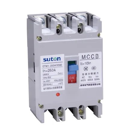
Related SUTON technical resources
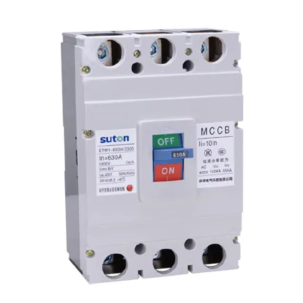
Use the linked product and related guides as procurement starting points, then verify the offered device against the project study. Similar-looking MCCBs can have different ratings, terminals, trip functions and approvals.
Educational video
The following educational video supports the underlying electrical concept and does not replace project calculations or manufacturer instructions.
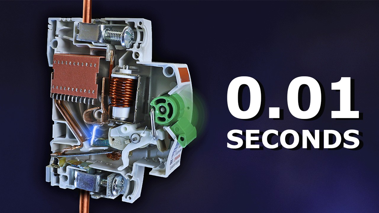
Watch Why Circuit Breakers Don’t Protect People on YouTube.
Frequently asked questions
Can every MCCB be reverse fed?
No. Suitability must be confirmed for the exact breaker, trip unit, accessories and approval conditions.
Does the absence of LINE and LOAD labels prove suitability?
No. Use the current manufacturer instructions and written model-specific evidence.
Can the load side remain live when the breaker is open?
Yes, in a multi-source or backfeed system conductors on either side may be energized, so the isolation procedure must identify every source.