


MCCB for generator protection must be selected from the generator duty, system arrangement and protection study—not from generator kVA alone. Confirm rated voltage and frequency, maximum continuous current, generator short-circuit contribution over time, neutral and earthing arrangement, conductor capacity, starting or step-load performance, and coordination with downstream devices. The MCCB must carry normal and permitted transient current while clearing faults within the generator, cable and switchboard withstand limits. A utility-fed breaker setting cannot be copied automatically because a generator can provide lower and decaying fault current. The responsible engineer must approve the exact breaker and settings for the installed generating set.
Why a generator source changes breaker selection
A generator does not behave like a stiff utility source. Its fault contribution is influenced by machine reactance, excitation system, governor response and protective controls, and it changes during the fault. The available current at the breaker can be high initially and then decay. A setting that trips quickly on utility fault current may respond much more slowly when the same bus is supplied only by the generator. Obtain a time-dependent fault model or manufacturer data rather than using only a transformer-style symmetrical current value.
Distinguish the generator main breaker from downstream feeder breakers. The main breaker may need to protect the generator leads and coordinate with generator protective relays, while outgoing MCCBs protect individual loads. If the system can operate in parallel with the utility or another generator, study every operating mode. The highest fault duty may occur in parallel operation, while the lowest fault current and most difficult detection may occur in island mode.
| Generator input | Selection effect | Required evidence |
|---|---|---|
| Rated voltage, frequency and current | Defines continuous duty | Nameplate and alternator datasheet |
| Subtransient, transient and steady fault data | Determines current available to trip protection | Generator fault-decrement data |
| Earthing and neutral arrangement | Affects ground-fault path and pole decision | Single-line and earthing study |
| Utility-parallel or island modes | Changes maximum and minimum fault levels | Fault study for each operating mode |
| Load steps and motor starting | Can produce normal transient current | Load schedule and starting study |
| Generator protection relays | Must coordinate with MCCB functions | Relay philosophy and setting sheet |
Use project calculations and the generating-set manufacturer’s data. This table does not provide universal settings.
Calculate normal current without ignoring load steps
Convert the generator rating to current using the correct phase arrangement, voltage and power factor assumptions, then compare the result with the nameplate and manufacturer documentation. Apply the required design margin and installation derating under the project rules. A breaker selected only to the nameplate current may nuisance-trip during an accepted motor start or large step load, but oversizing it can leave conductors and generator windings insufficiently protected.
Review the load sequence produced by the automatic transfer or generator controller. Elevators, pumps, compressors and large transformers may be connected in steps specifically to control voltage and frequency dip. Plot these permitted transients against the breaker curve. If a transient enters the trip band, revise the protection or load sequence using documented engineering—not by turning the pickup dial upward without checking fault performance.
Study both maximum and minimum fault current
Maximum fault current determines whether the breaker can interrupt the duty at the actual voltage. Minimum generator fault current determines whether the trip function can detect and clear the fault before damage occurs. Keep the MCCB’s continuous rating, frame size, trip-unit rating and breaking capacity separate. IEC 60947-2:2024 defines the circuit-breaker product scope; use the edition and local adoption specified by the project.
OSHA 1910.303 states that interrupting equipment must have adequate rating for nominal voltage and available current, and that circuit characteristics and protective devices must be coordinated. The rule does not produce the setting; it reinforces why the actual source and circuit must be studied.
Coordinate the MCCB with generator protection
A generator may use separate protection for overcurrent, earth fault, reverse power, loss of excitation, under/overvoltage, under/overfrequency or differential conditions. Do not assume an MCCB supplies these functions. Map each credible abnormal condition to the device intended to detect it, the device that opens the circuit, and the required time. Where a relay trips the MCCB through a shunt trip or undervoltage release, verify control voltage, stored energy and fail-safe behavior.
Review selectivity with downstream breakers, but do not preserve selectivity at the cost of generator damage. A generator may have limited thermal and electromagnetic withstand during faults. Use the alternator manufacturer’s damage limits and the approved protection philosophy. The MCCB trip-settings guide explains how to document adjustable functions, while the ground-fault guide addresses another function that depends on the earthing arrangement.
Check transfer and parallel-operation scenarios
For standby systems, verify breaker behavior during transfer, retransfer, maintenance bypass and testing. Interlocks must prevent unintended source paralleling unless the system is designed for it. For intentional paralleling, the MCCB selection becomes part of a wider synchronization and protection scheme. Directional power and generator-specific protection generally require dedicated relays rather than an ordinary MCCB trip unit.
Do not confuse this low-voltage application with a high-voltage generator circuit breaker. IEC/IEEE 62271-37-013 covers specified high-voltage generator circuit-breaker applications above 1 kV; it is not the product standard for an ordinary low-voltage MCCB. Naming the correct equipment class prevents an invalid specification.
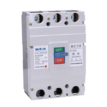
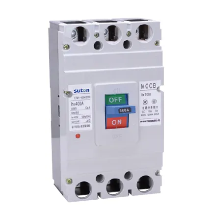
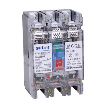
Review the SUTON ETM1 MCCB range as a product starting point, then request confirmation for the actual generator conditions. The circuit-breaker types guide provides the parent overview.
Build an approval record that can be audited
Record the exact catalog code, frame and trip rating, poles, voltage, breaking capacity, trip-unit type, settings, terminals, accessories, mounting arrangement and document revision. Keep the as-designed, as-installed and as-left information separate. A family brochure is not enough when several breaking capacities or trip units share the same enclosure. List every exception and identify who accepted it.
The final technical file should include the single-line diagram, fault-current study, protection study, conductor schedule, panel drawing, manufacturer instructions, required certificates and commissioning results. If a value comes from a calculation, state the source inputs and revision. If it comes from a manufacturer table, identify the exact table and device combination. This prevents a later replacement from being approved merely because it fits the opening.
Commissioning and safe-work boundary
Before energization, verify device identity, settings, pole arrangement, conductor placement, terminal preparation, tightening method, barriers, labels, handle operation, auxiliary functions and mechanical interlocks. Testing and fault studies must be carried out or approved by qualified people under the adopted rules. This article supports specification work and does not authorize energized work.
After a serious fault or unexplained trip, do not simply reset the breaker. Investigate the cause, inspect the breaker and connected equipment as required by the manufacturer, and confirm that the protection settings remain correct. Record any replacement, conductor work or setting change. Restore covers and interlocks before the approved energization sequence.
Information to include in an RFQ
Give bidders the system voltage and frequency, AC or DC duty, poles and neutral arrangement, normal current, calculated maximum and minimum fault current, required breaking capacity under the named standard, trip functions and settings, utilization duty, conductor and terminal details, accessories, control voltage, mounting, ambient conditions and required documents. Ask for a completed compliance schedule rather than an unqualified family datasheet.
Require the offered model to be decoded in full. Options such as electronic trip units, earth-fault functions, shunt trips, undervoltage releases, auxiliary contacts and motor operators can change the product code and wiring. An accessory shown in a brochure photograph is not automatically part of the quotation.
Questions to resolve before purchase approval
Ask who owns the fault-current calculation, who selects the settings, and which operating modes were included. Confirm the study revision matches the installed source, cable lengths, conductor sizes and downstream devices. Identify assumptions that still depend on vendor data. If two quotations use different trip technologies or breaking capacities, compare the complete protective performance instead of comparing only frame current and price.
Also confirm the documents that will arrive with the equipment: certified datasheet, time-current curves, installation instructions, accessory wiring, test certificates, setting record and maintenance guidance. State the language and file format required. Close technical comments before shipment whenever possible, because a late discovery about terminals, control voltage or pole arrangement can force panel changes and delay commissioning.
During bid review, place every answer beside the requirement and classify it as compliant, conditional or noncompliant. Do not accept a blank cell as compliance. Resolve alternative offers with the same engineering review applied to the base offer, and retain the final approved schedule with the purchase order for future reference.
Related SUTON technical resources
Use the linked product and related guides as procurement starting points, then verify the offered device against the project study. Similar-looking MCCBs can have different ratings, terminals, trip functions and approvals.
Educational video
The following educational video supports the underlying electrical concept and does not replace project calculations or manufacturer instructions.
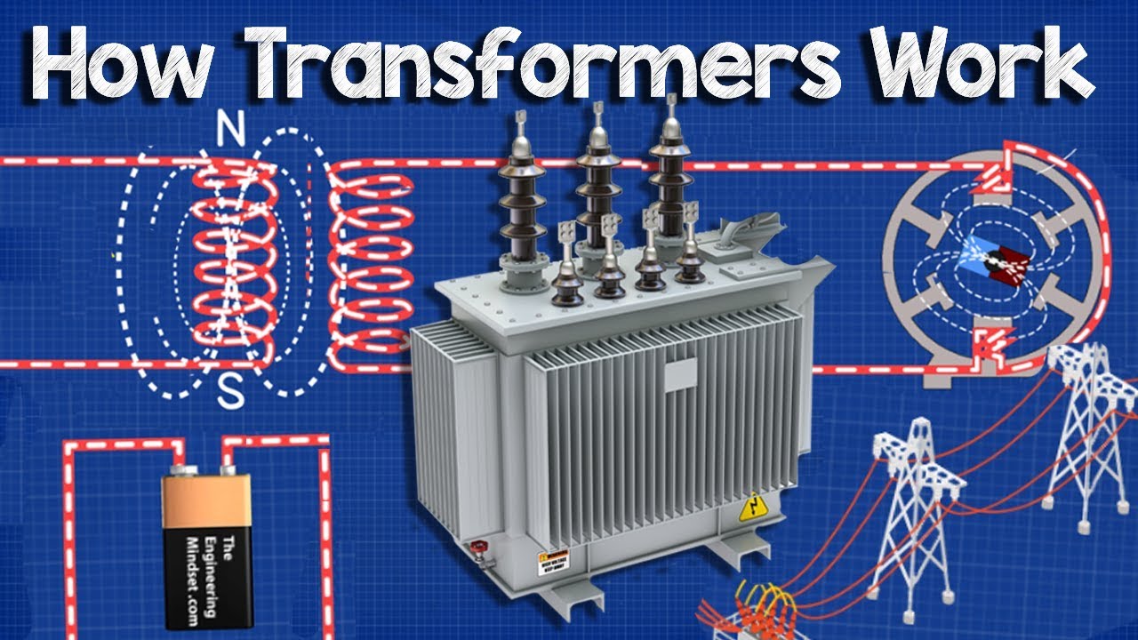
Watch How AC Generators Work on YouTube.
Frequently asked questions
Can generator kVA alone determine MCCB size?
No. Voltage, current, operating modes, fault decrement, conductor protection, load steps and coordination must also be studied.
Why can a utility breaker setting fail on generator supply?
Generator fault current can be lower and decay with time, so a setting that works on a stiff utility source may not clear a generator-fed fault as expected.
Does an MCCB provide all generator protection?
No. Generator-specific functions commonly require separate relays and a documented tripping scheme.