A busbar current rating calculation for an LV panel begins with the required load current, conductor geometry and installation conditions, then checks whether the complete assembly can carry that duty within its permitted temperature limits. Dividing amperes by a generic current-density value is only an early screening method. It does not verify an enclosed panel, its joints or its fault withstand. For selection, use documented conductor data and a suitable thermal method, then obtain assembly verification for the actual enclosure, circuit loading and connection arrangement. Keep all assumptions attached to the result so the supplier can review the same design.
For the wider connection and distribution context, use the busbar connection guide for panel builders. This calculation guide focuses on normal current selection rather than replacing that installation review.
Establish the current that the panel must carry
Begin with the approved load schedule and single-line drawing. Identify the incoming current, simultaneous outgoing loads, operating modes and any planned expansion. Separate a connected-load total from the design current that the electrical designer has justified. Diversity is a project assumption that needs an owner and a stated basis, not a convenient multiplier chosen to make an undersized bar appear acceptable.
Where a balanced three-phase load is specified by active power, current can be estimated from I = P / (sqrt(3) × VLL × power factor). Use watts for P, line-to-line volts for VLL and a dimensionless power factor. Include efficiency only when converting an output-power requirement to electrical input power. If apparent power S is already known in volt-amperes, use I = S / (sqrt(3) × VLL) instead; do not divide by power factor again.
For an illustrative 120 kVA balanced load at 400 V line-to-line, current is approximately 173 A. This is a load calculation, not a recommendation for a particular busbar section or SUTON model. The actual design must also account for unbalance, waveform distortion, service conditions and protection. Document whether the quoted load is continuous and which circuits operate at the same time.
Define the conductor and its environment
A calculation needs material grade, length, width, thickness, orientation, spacing and the number of parallel conductors per phase. Identify joints, bends and connections as well as straight lengths. Record whether the bars are bare, plated or insulated, and use the manufacturer's actual construction details. An exterior photograph cannot reliably establish hidden conductor dimensions or material.
Next define ambient temperature, enclosure dimensions, ventilation, mounting arrangement and heat from neighboring equipment. An open-air table and an enclosed assembly are different thermal situations. A compact branch system may have closely spaced components and local heat sources that a bare-bar estimate does not represent. Write down those differences before using a published table or calculation tool.
The Copper Development Association busbar reference describes rectangular copper ampacity information under specified frequency, surface and temperature conditions. Its conditions should travel with any value taken from the tables. It does not directly establish a rating for a different material, insulated bar arrangement or enclosed product.
Use area and current density as screening inputs
For a rectangular solid section, geometric area A equals width multiplied by thickness, with both dimensions expressed in the same length unit. An assumed 20 mm by 5 mm bar has 100 mm² of geometric area. Dividing a hypothetical 180 A by that area gives an average current density of 1.8 A/mm². These numbers are illustrative and are not an approved operating point.
Current density summarizes loading per unit area, but it does not contain the heat-transfer information needed to determine temperature. Two arrangements with the same area can differ in exposed perimeter, orientation, proximity to other bars and enclosure cooling. Parallel bars also need a suitable current-sharing and connection design. Do not multiply a single-bar rating by the number of bars without checking how that arrangement has been assessed.
The practical use of a screening calculation is to reject an obviously unsuitable starting concept or identify what requires more detailed assessment. It should lead to a documented thermal review, not become a substitute for one. If a vendor proposes a current-density rule, ask for its material, temperature and installation assumptions and how the finished assembly is verified.
Estimate resistance and losses with consistent units
The basic DC relation R = rho × L / A connects resistance to material resistivity, length and cross-sectional area. With rho in ohm-metres and length in metres, area must be in square metres to obtain ohms. Convert mm² carefully: 100 mm² equals 0.0001 m². Use a resistivity appropriate to the specified material grade and temperature rather than treating all copper or aluminum as identical.
Power dissipated in a resistive path is P = I²R. Suppose an illustrative path, including the boundary explicitly stated by the designer, has resistance 0.00015 ohm at the calculation temperature. At 200 A the arithmetic loss is 6 W. This does not predict the conductor temperature; it only estimates electrical heat generation within that defined path. Actual AC resistance, joints and nearby equipment may require additional treatment.
If comparing materials, keep length, temperature, frequency and calculation boundary consistent. A low resistance for a straight bar cannot be compared fairly with the measured resistance of another complete assembly including joints. The separate copper versus aluminum busbar guide explains the additional space, connection and purchasing questions that material selection introduces.
Close the thermal balance with an applicable method
A conductor reaches an operating temperature when its heat generation and heat removal are balanced under the relevant conditions. Heat transfer depends on more than cross-section: exposed surfaces, convection, radiation, conduction into connections and the enclosure environment all matter. This is why a resistance calculation alone cannot produce a verified current rating.
Ask the assembly manufacturer which verification approach applies to the offered construction and what conditions are covered. Retain the applicable reference design, test or assessment documents rather than a spreadsheet result without a traceable basis. The IEC 61439-1 official publication overview identifies the general construction and verification framework for low-voltage assemblies and its use with the applicable product part. The public overview itself is not a thermal test report.
Avoid quoting a single universal temperature-rise limit for every component. Conductors, terminals, insulation and accessible parts can be subject to different requirements and limitations. The design review must check the relevant boundaries for the actual assembly and applicable standard. A supplier response should identify the permitted service conditions as clearly as the nominal ampere rating.
Review calculation inputs and acceptance evidence together
This table connects the screening calculation to the documents needed for an equipment decision. It deliberately avoids a universal amps-per-square-millimetre rule. Resolve each item for the installed configuration before treating the selection as approved.
| Review item | Calculation input | Verification required |
|---|---|---|
| Load duty | Design current and simultaneous circuit loading | Declared assembly current under matching conditions |
| Conductor | Material grade, length and actual section | Approved drawing and conductor specification |
| Thermal environment | Ambient, enclosure and adjacent heat sources | Applicable temperature-rise verification |
| Connections | Joint and terminal configuration | Manufacturer installation and connection evidence |
| Fault duty | Prospective RMS and peak current, clearing conditions | Assembly withstand or approved conditional rating |
| Future changes | Planned loads and permitted additions | Conditions requiring design reassessment |
Use the table during quotation review, not only at final inspection. Missing enclosure information or unclear simultaneous loading can change the selection materially. Resolving such inputs early gives the manufacturer a fair opportunity to offer an appropriate arrangement and prevents purchasing from comparing ratings based on different assumptions.
Check joints, terminals and outgoing branches
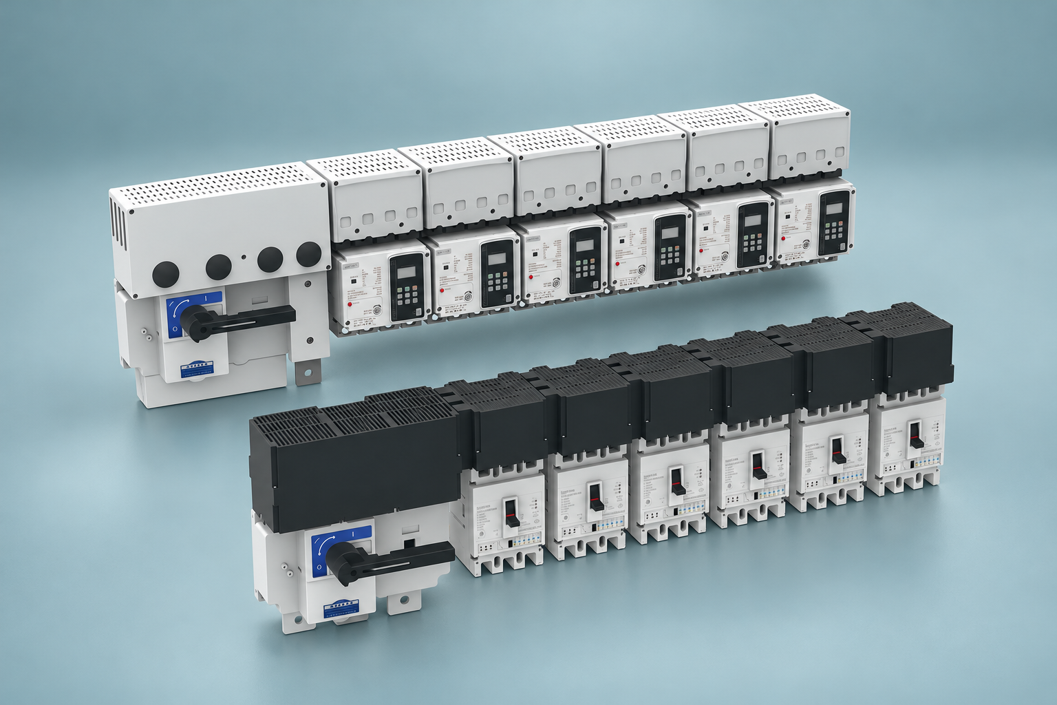
The incoming busbar is only one part of the current path. Review joints, device terminals, branch conductors and cable landing arrangements for the duty they actually carry. A large main section cannot compensate for an incompatible terminal or a connection outside the approved design. Confirm conductor material compatibility and the installation method for every site-made interface.
Obtain manufacturer instructions for connection components, torque application and inspection. Do not infer the required torque from bolt size alone. Preserve the identity of approved accessories and record any field substitution for review. The MCB terminal torque and connection guide addresses related terminal concerns; busbar assembly instructions still govern the actual system connection.
Also review the load distribution among branches. A proposed total current may be acceptable only with defined circuit loading. One heavily loaded branch can create a local condition that a simple sum or average does not show. Match branch count, device arrangement and enclosure integration to the manufacturer's applicable evidence.
Verify fault duty separately from continuous current
The available short-circuit current and protective-device operation determine a different set of stresses from normal loading. Check the assembly's declared RMS duty with duration, peak duty or conditional rating as applicable. Do not assume a thick bar or a high-rated breaker proves the complete assembly is suitable.
Use the busbar short-circuit withstand guide to organize the fault-duty document request. Coordinate it with the MCB breaking-capacity selection guide for device interruption requirements. Keep the two reviews tied to the same source arrangement and protective settings so a later design change is assessed consistently.
Review the actual SUTON enclosed system
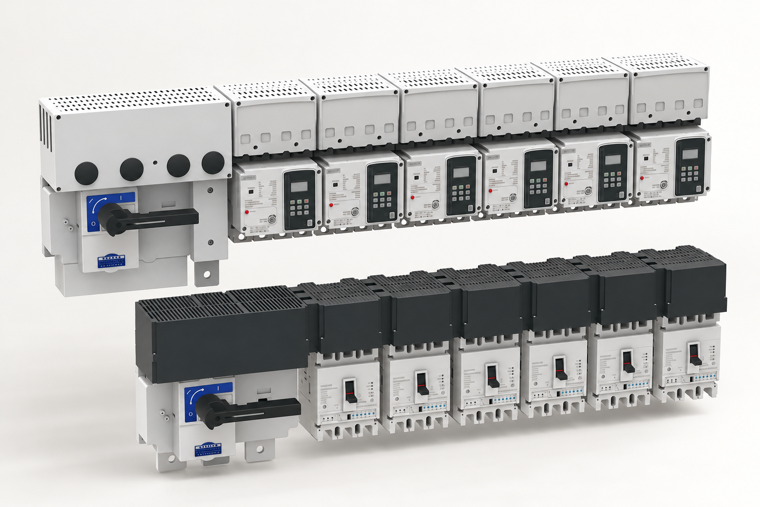
The SUTON ETFZX enclosed busbar system is presented for integrated low-voltage cable branching and distribution. Use its model identification and drawings to discuss the required current, branch arrangement and cabinet space. The product page contains performance descriptions, but an exterior illustration does not independently verify internal dimensions, allowable loading or fault capability for an order.
Send SUTON the load schedule, voltage and frequency, ambient conditions, enclosure details, connection arrangement and required fault duty. Request the rating conditions and verification evidence for the exact offered model. The product description includes different temperature-related claims, so do not select one figure as a universal project limit without model-specific clarification. Preserve the response with the approved drawing and purchase specification.
Frequently asked questions
Can I select a busbar using only current density?
Use current density as an initial screening value only when its assumptions are clear. Final selection needs thermal and connection assessment for the actual construction, enclosure and loading, plus separate verification of fault duty and other applicable assembly requirements.
Does doubling bar area double its current rating?
Do not assume a linear relationship. Geometry, exposed surface, cooling, AC effects, parallel current sharing and connections can change the result. Use an applicable calculation or verified arrangement and obtain the manufacturer's declared rating conditions.
What must accompany a supplier's ampere rating?
Request the exact assembly model and drawing, conductor specification, service conditions, circuit-loading assumptions, thermal verification, connection instructions and applicable short-circuit declaration. The rating is meaningful only when these conditions match the intended installation.
Educational video
Ohms Law Explained – The basics circuit theory by The Engineering Mindset. This educational video explains voltage, current and resistance as background for conductor loss calculations. It does not establish an assembly ampacity or approve installation work.