A manual changeover switch requires a person to initiate and carry out a source transfer. An automatic transfer switch adds a control system that detects source conditions and operates the transfer arrangement according to a defined sequence. Neither description establishes uninterrupted power, protection coordination or permission to parallel two sources. For a panel buyer, the main choice is the acceptable interruption and operating response, followed by a verified switching arrangement. This guide compares the specification questions for manual and automatic transfer, using SUTON's HGL(ETGL)/Z manual transfer load-disconnector family as a product reference. It does not present that product as an automatic transfer switch.
Define the required outcome during a supply failure
Ask what must happen when the normal supply becomes unavailable. A small process may tolerate a controlled shutdown followed by an authorized manual transfer. A continuously staffed installation may accept that response while an unattended installation may require automatic detection and operation. Critical loads can need a different continuity solution, including energy storage or an uninterruptible supply, because even an automatic transfer can involve an interruption.
Write the maximum acceptable interruption, the responsible operator, the source availability assumptions and the restoration policy. Include failures during nights, weekends and maintenance periods. A system described as “backup ready” is incomplete if nobody is assigned to perform a manual transfer or if the alternate source cannot support the required load. Choose the operating concept before asking suppliers to price a switch.
Separate operating mode from transition method
Manual and automatic describe how transfer is initiated and carried out. Open and closed transition describe the relationship between source connections during the transfer. These are different questions. An open-transition arrangement disconnects one source before connecting the other; a closed-transition arrangement includes a period of source overlap and requires the appropriate engineering and approvals. Do not assume a switch supports overlap because it has two incoming connections.
The project's single-line diagram should show which source combinations are permitted. If parallel operation is not allowed, the specification must make that restriction explicit and identify the means that enforce it. Generator protection, utility requirements and the source characteristics can all affect the decision. A generic transfer-switch illustration is not enough to approve the installation.
Understand what the SUTON manual product page establishes
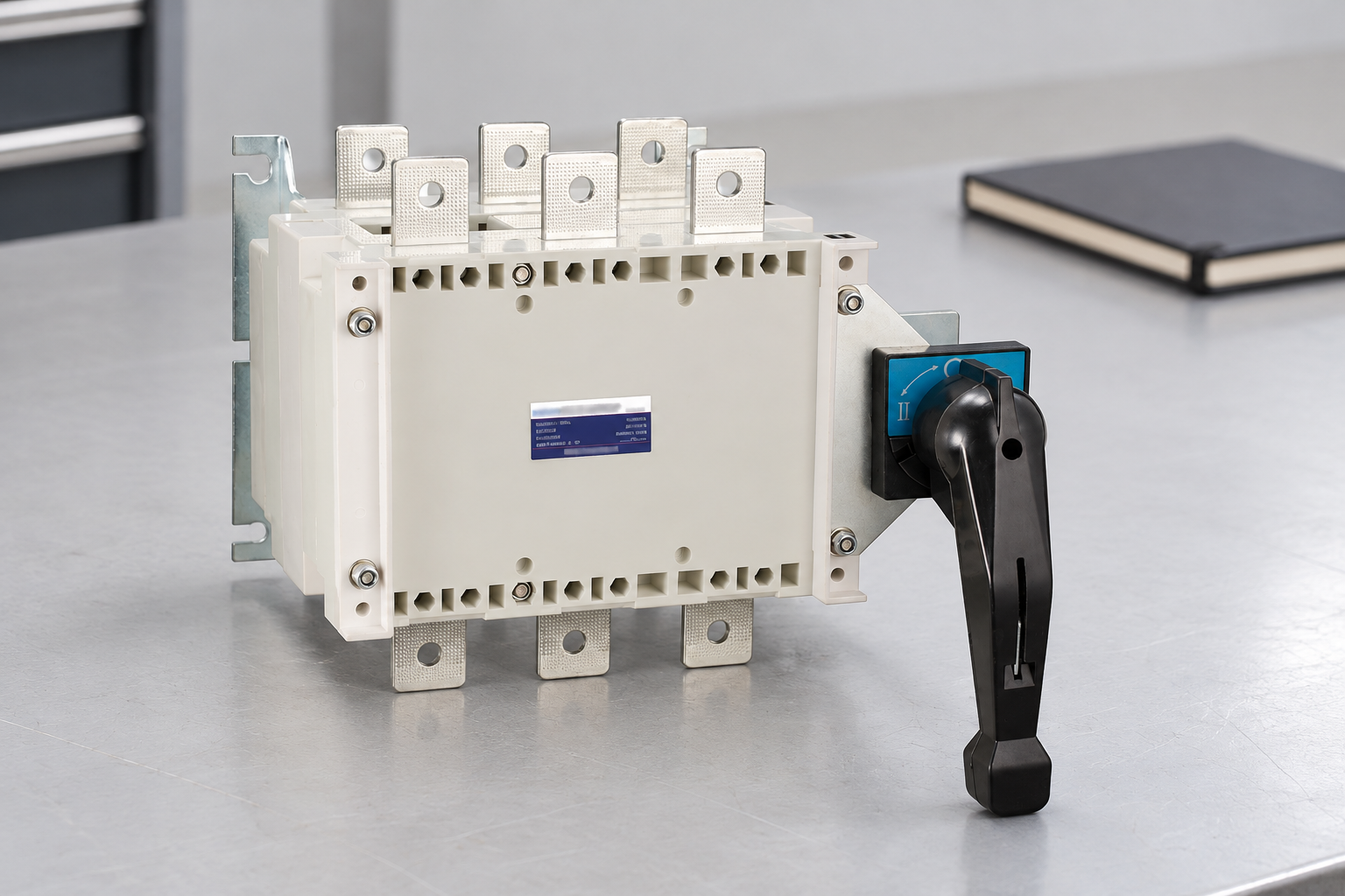
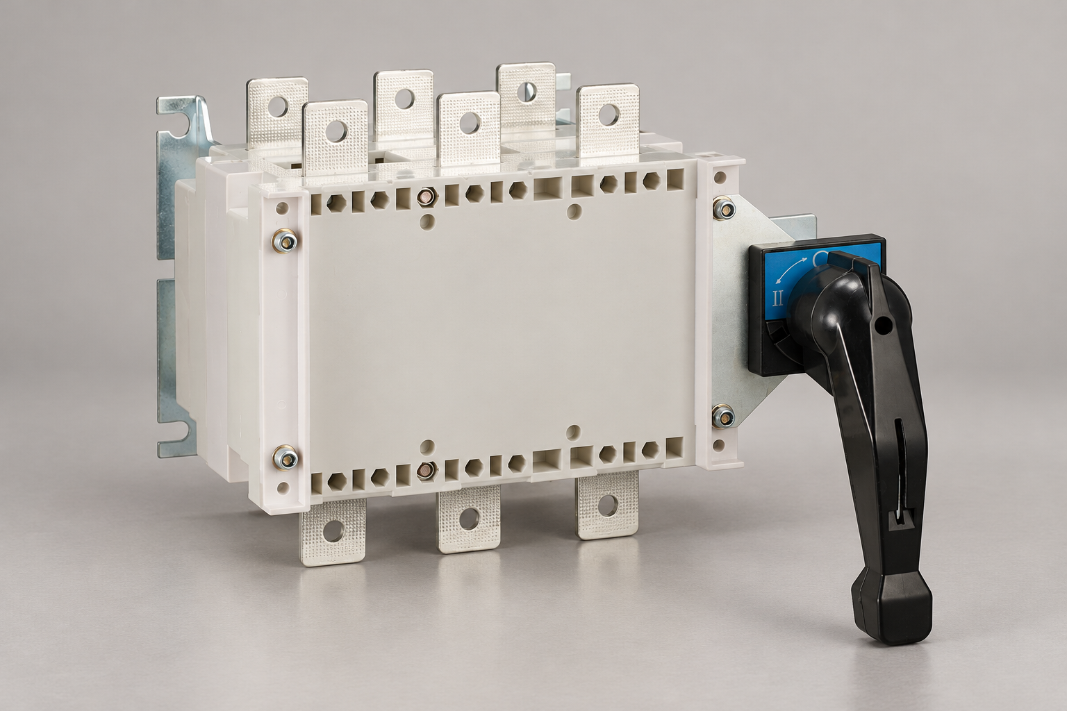
The HGL(ETGL)/Z transfer load disconnector is described for switching between two low-voltage circuits or two load devices. Its published operating methods include a handle mounted directly on the switch and a handle operated from outside the cabinet door. Three-pole and four-pole arrangements are described, with a switchable neutral option in the four-pole configuration. Auxiliary contacts and bridge connections are configuration questions to specify.
The product page also distinguishes vertical and horizontal arrangements and states that a viewing window can be supplied for certain configurations, with an exception for the Z1 model. Treat this as a family-level description. Request the exact arrangement, pole configuration, contact-state information, terminal drawing and accessory list for the offered code. A viewing feature on one configuration must not be assumed on another.
Nothing in that description alone establishes source monitoring, automatic generator starting, transfer delays, synchronization or a complete automatic controller. If the project needs those functions, ask for a separately documented automatic transfer solution. Do not turn a manual product into an ATS in the purchase schedule by adding the word “automatic” to its name.
Compare the complete operating arrangements
| Requirement | Manual arrangement | Automatic arrangement |
|---|---|---|
| Initiation | Authorized person identifies need | Controller evaluates defined source conditions |
| Operation | Approved manual mechanism | Documented powered operating sequence |
| Attendance | Operator availability is essential | Unattended response still needs failure handling |
| Transition | Confirm actual permitted source states | Confirm actual permitted source states |
| Neutral | Follow the approved earthing design | Follow the approved earthing design |
| Maintenance | Keep exact manual and procedure | Also retain control settings and alarms |
| Continuity | Interruption must be acceptable | Automatic does not mean uninterrupted |
The table compares project requirements rather than promising a universal advantage for either approach. An inexpensive manual switch can become a poor operational choice if the site cannot provide an authorized operator when needed. Conversely, automation adds control components, settings and maintenance obligations that should have a stated purpose. Compare the whole delivered system, including the response plan and evidence package.
For the broader switching context, the isolator switch planning guide covers isolation boundaries and panel integration. A source-transfer function adds another set of conditions; it does not remove the need to identify the correct maintenance isolation points.
Review neutral and earthing arrangements explicitly
A three-pole and a four-pole transfer proposal may behave differently with respect to the neutral. The appropriate arrangement depends on the earthing system, source neutral connections, protective devices and applicable rules. The decision should come from the responsible design, not from a blanket claim that switching more poles is always safer or that a generator always requires the same arrangement.
Request a diagram for each permitted operating state and identify where neutral-to-earth connections exist. Consider residual-current protection and how alternate-source operation affects its intended behavior. Retain the engineering decision with the equipment schedule. The three-pole versus four-pole switch-disconnector comparison explains the pole-selection questions without replacing the transfer-system study.
Check source capacity and protective coordination
The transfer switch carries the connected load, but it does not automatically provide every overcurrent protective function. Identify the protection on each source, the prospective fault current under each supply condition and the protective-device combinations applicable to the transfer equipment. The generator condition may differ substantially from the utility condition, so one assumed fault level is not sufficient for every mode.
Ask for the applicable switch rating, short-circuit duty and required upstream protection for the exact combination. Avoid comparing a withstand rating with a breaker's interruption rating as though they were interchangeable. The switch-disconnector making and breaking capacity guide provides the adjacent rating context. The project assessment must still address the actual transfer arrangement.
Specify automatic functions individually when they are required
For an automatic proposal, list the required source measurements, acceptable operating conditions, delays, generator start interface, transfer sequence, restoration behavior, alarms and manual control provisions. Describe how the system behaves if the alternate source is unavailable or a control supply fails. Confirm which settings are adjustable, who may change them and how the final configuration is recorded.
An ATS should not be accepted only because it moves during a demonstration. The acceptance plan should verify the expected sequence against the approved design, including abnormal conditions that the project requires. Testing must follow an authorized method and protect connected loads. This article provides procurement questions, not instructions for simulating live supply failures.
Plan manual operation as an organizational responsibility
For a manual arrangement, identify who may operate it and how that person determines whether transfer is appropriate. Keep source identification, switch labels and the approved sequence aligned with the drawings. The operating position must remain accessible in the conditions under which the transfer may be needed. A switch behind an obstructed door is not a dependable response plan.
State what happens to process equipment during interruption and restoration. Motors, control systems and electronic loads can have their own restart conditions. The changeover function should be coordinated with those requirements rather than evaluated only as a mechanical movement between positions. Document any loads that must remain disconnected until a separate release is given.
Preserve a separate maintenance isolation plan
A transfer switch can have conductors connected to more than one source. An alternate source may remain present when the normal source is disconnected. The maintenance plan must identify those boundaries independently of normal operating positions. Include auxiliary supplies and any automatic commands that can change the equipment state.
HSE's guidance on working on electrical equipment supports planned work and secure control of energy. HSE's electrical safety questions also addresses secondary sources in installations. These sources support the distinction between normal source transfer and making a work boundary safe; they do not certify a particular transfer switch or supply a universal operating sequence.
Send suppliers a comparable transfer brief
A useful inquiry identifies both sources, the connected load, voltage and frequency, pole and neutral arrangement, fault levels, protection, operating mode, transition requirement, enclosure, installation orientation and required accessories. Add the acceptable interruption, attendance assumptions and automatic functions where applicable. Request drawings and manuals for the exact offered configuration before approval.
During review, identify exceptions clearly. If a supplier quotes a manual HGL(ETGL)/Z arrangement against a requirement for automatic transfer, resolve that difference before price comparison. If a quotation assumes a viewing window, bridge connection or auxiliary contacts, check that they are included in the actual code and scope. Preserve the final approved schedule so later substitutions cannot quietly change the operating concept.
Record the final delivered arrangement
Keep the operating-mode decision, source diagrams, pole selection, accessory codes, controller settings where applicable and acceptance results in one revision-controlled handover package. Identify the personnel responsible for later changes. A replacement controller, generator or neutral arrangement can change the assumptions behind an earlier approval even when the transfer switch current rating remains the same. Review those changes before returning the installation to service. Record the actual equipment codes rather than relying on the trade name of the original proposal.
Frequently asked questions
Does automatic transfer mean uninterrupted power?
No. The transfer sequence may include an interruption. Continuity depends on the complete power architecture, source conditions, transition method and any energy-storage or UPS provision.
Can the HGL(ETGL)/Z be called an ATS from its product description?
No. Its published manual operating arrangements do not establish the source monitoring, automatic controller and operating sequence needed to make that claim.
Is four-pole transfer always the correct choice for a generator?
No universal rule can be given here. Neutral switching must follow the approved source, earthing and protection design and the applicable installation requirements.
Educational video
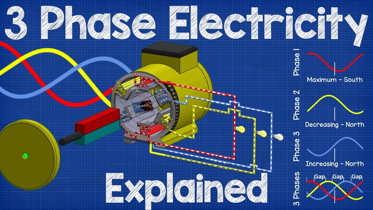
How Three Phase Electricity works – The basics explained by The Engineering Mindset. This independent educational explanation supports identification of three-phase supply arrangements when reviewing normal and alternate sources. It does not provide a transfer-switch wiring diagram or approve a neutral arrangement.