


MCCB temperature derating is the reduction or adjustment of allowable continuous current, trip performance or enclosure loading when the actual ambient differs from the reference condition. The relevant temperature is not simply the room thermostat reading. It can include enclosure heat rise, adjacent devices, conductor losses, solar or process heat, altitude and ventilation. Use the exact SUTON model, trip unit, installation arrangement and manufacturer curve or table. Never apply a generic percentage to an MCCB family because the frame size and trip technology can have different limits.
Identify which temperature is being derated
Separate at least four questions in the design record. First, what ambient temperature does the breaker rating assume? Second, what continuous current is permitted at the actual ambient? Third, how does the trip unit’s long-time function behave at that temperature? Fourth, what heat rise is acceptable inside the complete enclosure? A breaker can have an ambient-current adjustment while the panel assembly still needs a separate temperature-rise review. Conversely, an enclosure may be hot even when the breaker room temperature appears acceptable.
Read the product table literally. Fuji Electric’s ambient-temperature explanation demonstrates that an MCCB derating answer is tied to the exact family and ambient condition. Eaton’s derating-curve note likewise directs the designer to the breaker-specific curve. These references explain the method; they do not supply SUTON settings.
| Heat source or condition | What can change | Evidence or check |
|---|---|---|
| High external ambient | Continuous current capability and trip response | Exact manufacturer temperature table or curve |
| Several loaded devices in one enclosure | Internal air temperature and assembly heat rise | Panel thermal calculation and spacing/ventilation data |
| Large conductors or loose terminations | Local hot spots and terminal damage | Conductor schedule, torque procedure and inspection |
| Solar, process or transformer heat | Starting ambient above room condition | Site temperature survey or thermal design input |
| Altitude and reduced cooling | Heat dissipation and possibly dielectric margins | Project altitude and manufacturer application limits |
| Electronic trip unit and accessories | Sensor, control or accessory operating limits | Exact trip-unit and accessory manuals |
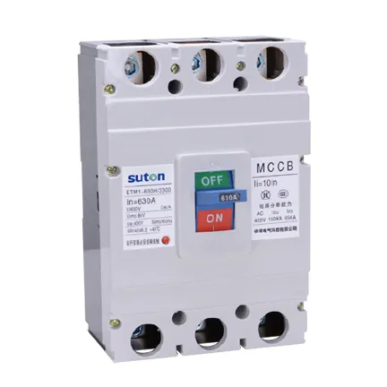
The table identifies review inputs. It does not provide universal derating percentages.
Calculate the installed thermal condition
Start with the actual load schedule, diversity assumptions, conductor losses and simultaneous loading. Add heat from adjacent breakers, contactors, power supplies, transformers, busbars and control equipment. Check the enclosure’s internal dimensions, material, mounting orientation, ventilation, fan or heat-exchanger performance and solar exposure. If the panel is installed in a hot plant room, use the expected worst case rather than a mild outdoor average.
Do not solve a thermal problem by increasing the breaker frame. A larger device may change fault ratings, terminal sizes, selectivity and available space while leaving the enclosure heat source unchanged. If continuous current must be limited, document the load restriction, ventilation change, spacing, busbar change or alternate device that resolves it. Keep the calculation traceable to the final drawing revision.
Check trip settings and conductor protection together
Temperature can affect long-time pickup, conductor ampacity and nuisance-tripping margin. Compare the derated continuous duty with the conductor installation method, grouping, insulation rating and terminal limits. Then review short-time and instantaneous settings separately. A setting that prevents nuisance operation during heat soak must still clear the minimum fault current within the conductor and equipment withstand limits.
For an electronic MCCB, confirm sensor location, trip-unit ambient range, control-power limits and any temperature compensation stated by the manufacturer. For a thermal-magnetic device, use the published characteristic and adjustment conditions. Do not transfer a curve from another frame or trip-unit family.
Verify the complete assembly
IEC 60947-2:2024 covers low-voltage circuit breakers within its scope, while the panel assembly has its own thermal and installation evidence. Check terminal torque, conductor cross-section, busbar joints, barriers, clearances, cable bend radius and heat paths. A hot terminal can be caused by poor preparation or loose hardware, not only by a high ambient condition.
After commissioning, record temperatures under representative load and investigate abnormal differences between phases or terminals. Thermography is a diagnostic aid, not a replacement for the manufacturer’s ratings or a safe-work procedure. Trend the result after load changes, enclosure modifications or seasonal temperature changes.
RFQ questions for temperature derating
- What reference ambient and mounting arrangement apply to the exact model?
- What continuous-current table or curve applies to the chosen frame and trip unit?
- Are electronic trip units, neutral protection and accessories subject to separate limits?
- What terminal, conductor and enclosure assumptions support the rating?
- How should altitude, solar or process heat be considered?
- What panel thermal evidence and acceptance measurements are required?
- Which document revision and model code will appear on the final schedule?
Use the SUTON ETM1 MCCB page as a product starting point and request the exact ambient-current data for the offered configuration. The circuit-breaker types guide is the parent overview, the motor-feeder selection guide covers starting-current coordination, the generator-protection guide covers source-specific fault duty, and the Icu versus Ics guide supports the fault-duty review.
Build an approval record that can be audited
Record the exact catalog code, frame, rated current, poles, voltage, breaking capacity, trip-unit type, settings, terminals, accessories, mounting arrangement and document revision. Keep the as-designed, as-installed and as-left information separate. A family brochure is not enough when several ratings or configurations share an enclosure.
The technical file should include the single-line diagram, fault-current study, protection study, conductor schedule, panel drawing, manufacturer instructions and commissioning results. If a value comes from a calculation, state the source inputs and revision. If it comes from a manufacturer table, identify the exact device combination.
Commissioning and safe-work boundary
Before energization, verify device identity, settings, pole arrangement, conductor placement, terminal preparation, tightening method, barriers, labels, handle operation, auxiliary functions and mechanical interlocks. Testing and fault studies must be carried out or approved by qualified people under the adopted rules. This article supports specification work and does not authorize energized work.
After a serious fault or unexplained trip, do not simply reset the breaker. Investigate the cause, inspect the breaker and connected equipment as required by the manufacturer, and confirm that settings remain correct. Record any replacement, conductor work or setting change.
Information to include in an RFQ
Give bidders the system voltage and frequency, AC or DC duty, poles and neutral arrangement, normal current, calculated maximum and minimum fault current, required breaking capacity under the named standard, trip functions and settings, utilization duty, conductor and terminal details, accessories, control voltage, mounting, ambient conditions and required documents. Ask for a completed compliance schedule rather than an unqualified family datasheet.
Require the offered model to be decoded in full. Options such as electronic trip units, earth-fault functions, shunt trips, undervoltage releases, auxiliary contacts and motor operators can change the product code and wiring. An accessory shown in a brochure photograph is not automatically part of the quotation.
Close the evidence loop before purchase approval
Place each supplier answer beside the project requirement and classify it as compliant, conditional or noncompliant. Do not treat a blank cell as compliance. Resolve alternative offers with the same technical review applied to the base offer, and retain the approved schedule with the purchase order. Confirm that the datasheet revision, drawing, setting sheet and installation instructions all describe the same catalog code and option package.
Ask who owns the fault-current calculation, who sets the protection, and which operating modes were included. Record assumptions that still depend on vendor data. This small discipline prevents a late discovery about neutral sensing, a mounting base, an ambient limit or an accessory from becoming a panel change after shipment.
At handover, keep the final model code, setting record, test results and marked-up single-line diagram together. Future maintenance staff should be able to see exactly which neutral function was approved and which conductors or sources were included in that decision.
Where the quotation offers alternatives, ask the supplier to identify every changed interface and every changed assumption. A different pole arrangement, connection kit or thermal limit can alter the panel drawing, coordination study and commissioning plan even when the front label appears similar.
Keep those clarifications with the approved purchase record so a later replacement is checked against the same interface and duty.
Include the final arrangement in the maintenance handover package for future maintenance and detailed technical review.
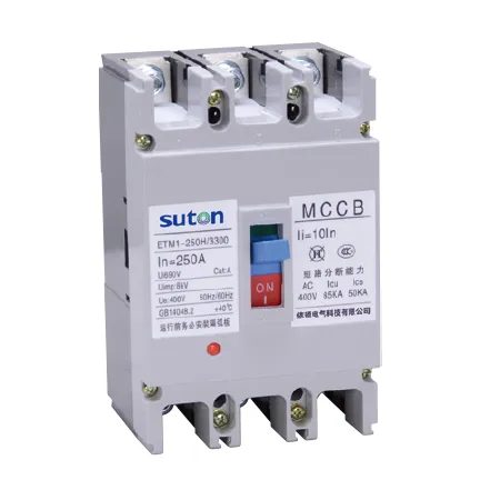
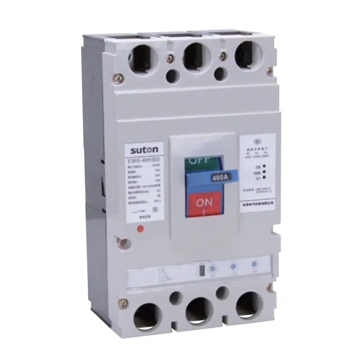
Related SUTON technical resources
Use the linked product and related guides as procurement starting points, then verify the offered device against the project study. Similar-looking MCCBs can have different ratings, terminals, trip functions and approvals.
Educational video
The following neutral educational video supports the electrical principle discussed here. It does not replace project calculations or manufacturer instructions.
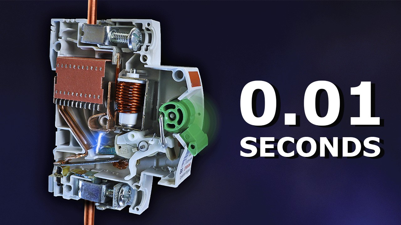
Watch Why Circuit Breakers Do Not Protect People on YouTube.
Frequently asked questions
Can I apply one derating percentage to every MCCB?
No. Derating depends on the exact frame, trip unit, ambient, mounting and manufacturer data.
Is room temperature the same as MCCB ambient?
Not necessarily. Enclosure heat rise, adjacent devices, solar or process heat can make the device ambient higher.
Does a larger frame automatically solve overheating?
No. It may change ratings and interfaces without removing the enclosure heat source.