


MCCB for motor feeder selection starts with the motor duty and the complete protection scheme, not the motor’s kilowatt rating alone. Record the motor nameplate current, starting method and duration, feeder conductor, system voltage, prospective fault current, and the overload device already present in the starter. Then choose an MCCB whose declared voltage and short-circuit ratings suit the installation, and whose trip characteristic permits a normal start while protecting the feeder. An MCCB does not automatically provide every motor-protection function. The responsible designer must verify the exact breaker, starter, overload relay or drive, and the applicable local rules together.
Where the MCCB fits in a motor feeder
A motor feeder can contain a supply breaker, cable, contactor, overload relay, motor, control circuit, and sometimes a soft starter or variable-frequency drive (VFD). The MCCB’s immediate job is to interrupt faults within its declared capability and to protect the feeder in coordination with the rest of the assembly. Depending on its trip unit and the approved design, it may also provide overload protection. However, a standard distribution MCCB should not be described as a complete motor-protection system without checking the actual starter arrangement and required functions.
Separate three questions in the single-line diagram. What protects the feeder conductor? What detects a motor overload or stalled rotor? What interrupts a short circuit without damaging the contactor and starter beyond the accepted coordination level? These are related decisions, but one device label rarely answers all three. IEC 60947-2 covers circuit breakers; the separate IEC 60947-4-1 family addresses electromechanical contactors and motor starters. Check the edition adopted for your project.
| Design input | Why it matters | Evidence to request |
|---|---|---|
| Motor nameplate and duty | Establishes normal running and thermal duty | Nameplate, duty cycle, service conditions |
| Starting method and time | Starting current must not be mistaken for a fault | Motor or starter starting-current profile |
| Feeder conductor | Protection must suit installed cable and derating | Cable schedule, installation method, ampacity study |
| Available fault current | Determines interrupting-duty requirement | Short-circuit study at the MCCB terminals |
| Starter and overload device | Defines which component handles motor overload | Exact model codes and coordination tables |
| Operating objective | Defines selectivity and restart expectations | Single-line diagram and approved protection study |
This is a decision checklist, not a table of universal settings. The actual values must come from the motor, installation and manufacturer data.
Start with the motor and its starting profile
The running current on a motor nameplate is not the highest current the feeder will see. A direct-on-line start can create a much larger transient; a soft starter changes the current-time shape; a VFD changes the input-current behavior again. The breaker must avoid nuisance operation during an acceptable start, including a difficult start under the specified load, without losing protection against real faults. Do not select a larger breaker merely because a smaller one trips during commissioning. First determine whether the event was expected inrush, an unusually long acceleration, a jam, an incorrect setting, low supply voltage, or an actual fault.
Ask for a current-versus-time starting trace or an engineering estimate that includes the driven machine, starting method, source impedance, and permitted voltage dip. Pumps, compressors, conveyors, fans, and high-inertia loads may have very different acceleration demands even with similar nameplate currents. NEMA’s motor-performance training material illustrates why starting current needs separate attention from full-load current. It is an educational reference, not a setting chart for a particular MCCB.
Include the number of starts per hour and the interval between starts. Repeated starts can affect motor and starter heating even where each individual start remains below an instantaneous pickup. For a motor with frequent reversing, plugging, jogging, or an unusually long acceleration, ask the motor and starter suppliers to confirm the allowable duty. The breaker curve alone cannot establish thermal acceptability of the complete drive train.
Coordinate the breaker with overload protection
Motor overload protection is not the same as feeder short-circuit protection. An overload relay or drive function may be selected to respond to sustained motor overcurrent, loss of phase, or stall, depending on the equipment. The MCCB must clear faults that exceed its protective threshold and remain coordinated with the downstream starter. Identify precisely which device will trip for each condition and how a trip is reset. If the MCCB’s thermal element is also part of overload protection, verify that its characteristic suits the motor and conductor rather than assuming that a current rating printed on the case is sufficient.
A magnetic-only motor circuit protector is not interchangeable with an ordinary thermal-magnetic MCCB simply because both fit an enclosure. Their intended system roles and required companion devices can differ. Likewise, a contactor is an operating switch, not an automatic short-circuit protective device by itself. The submittal should show the complete tested or accepted breaker-contactor-overload combination when coordination is required. Do not transfer a combination table from another brand, frame or trip unit to the offered equipment.
Local motor-protection rules and application details matter. An IEC-designed panel and a North American-listed motor circuit can require different evidence; the purchase order should name the destination rules before a supplier proposes a substitute. Where an overload function is omitted or assigned to another device, the technical file should explain the intended protective method and the authority for that choice.
Check voltage and short-circuit duty at the installation point
The available short-circuit current at the breaker line terminals may differ considerably from a value quoted at the transformer or at a distant switchboard. Obtain the fault study for the actual feeder location and compare it with the offered model’s declared breaking capacity at the real operating voltage. Keep continuous-current rating, frame size, trip-unit rating, and interrupting capacity as separate fields in the approval record. They are not four ways of stating the same value.
The electrical system can also change. A larger transformer, parallel generator, new utility supply, or shorter cable run may raise prospective fault current. A replacement MCCB selected using an old schedule may therefore be inadequate even if its ampere rating matches the previous device. OSHA 1910.303 requires adequate interrupting rating at the equipment’s nominal voltage and available current, and requires protective components to be coordinated so a fault can be cleared without extensive damage.
If a manufacturer offers backup or cascading protection, require evidence for the exact upstream and downstream combination. Do not add the ratings of two breakers or assume that a high-rated upstream device automatically upgrades every downstream component. The contactor, overload relay, cable, and panel assembly also need their own fault and coordination review.
Review time-current behavior rather than one ampere number
Plot the motor-start trace against the proposed breaker time-current curve. Include published tolerance bands, ambient effects, and the relevant minimum and maximum fault levels. The normal start should stay on the non-trip side with suitable margin, while faults must be cleared in the required time. If the curves overlap, the answer may be a different trip unit, a different starting method, a different protective combination, or a design change. Raising the instantaneous pickup without studying the reduced fault current at the end of a long feeder can leave a protection gap.
For an adjustable MCCB, record every setting in the panel schedule and commissioning sheet. Write down the basis for long-time pickup and delay, short-time pickup and delay if present, and instantaneous pickup. Where earth-fault protection is fitted, coordinate it with the grounding system and upstream/downstream protection. A front-panel dial should never be treated as a universal recipe. Use the manufacturer’s setting instructions and the engineer’s approved study for the exact model.
Thermal-magnetic and electronic trip units do not offer identical adjustment, indication, or tolerance. The planned thermal-magnetic versus electronic trip guide explains the broader trade-off; the MCCB setting guide covers how to document the protection functions. Neither replaces a motor-feeder coordination study.
Match the installation and control arrangement
Check the number of poles, neutral treatment where applicable, terminal type, conductor range, lug kit, mounting orientation, enclosure temperature, and ventilation. A breaker that is electrically suitable on paper can still be wrong for the panel if its terminals will not accept the specified conductor or if the operating handle conflicts with a door interlock. Confirm whether remote trip, undervoltage release, auxiliary status, or shunt trip is actually required. Each accessory has its own voltage and wiring requirements and may change the exact model code.
For VFD-fed motors, distinguish the breaker on the drive input from protection of the motor on the drive output. The drive manufacturer’s instructions may specify allowable upstream protective devices and restrictions on output switching. Do not place an MCCB in the drive output simply because the diagram needs a visible breaker symbol. For a soft-starter arrangement, verify the bypass, overload and fault-protection roles in both starting and running states.
Maintenance and operating practice belong in the design review. Decide whether the panel operator may reset after an overload, whether a fault requires inspection by qualified personnel, and which event records are available. Frequent unexplained trips are evidence of a system problem, not a reason to bypass protection. The ground-fault settings guide
A practical selection and approval sequence
- Gather the motor nameplate, load profile, starting method, starting time, starts per hour, and permitted voltage dip.
- Define the circuit role of the MCCB, contactor, overload device, drive or soft starter, and disconnecting means.
- Confirm system voltage, earthing arrangement, poles, conductor material and size, installation derating, and panel environment.
- Calculate maximum and minimum prospective fault current at the proposed breaker location.
- Compare exact device ratings and time-current curves with motor starting, conductor protection, and fault-clearing requirements.
- Check the manufacturer’s combination and coordination evidence for the complete starter assembly.
- Record the exact catalog code, accessories, settings, drawings, certificates required by the contract, and exceptions.
- Commission the installed combination and save as-left settings and test records.
At the request-for-quotation stage, ask bidders to fill out a compliance schedule instead of sending only a product-family brochure. The schedule should identify the proposed model, trip-unit variant, rated voltage, current, breaking capacity at the project voltage, control accessories, terminals, dimensions, and supporting document revision. If a feature is optional, it must be listed as part of the offered configuration rather than implied by a family photograph.
How SUTON equipment can enter the review
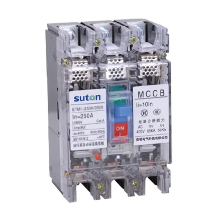
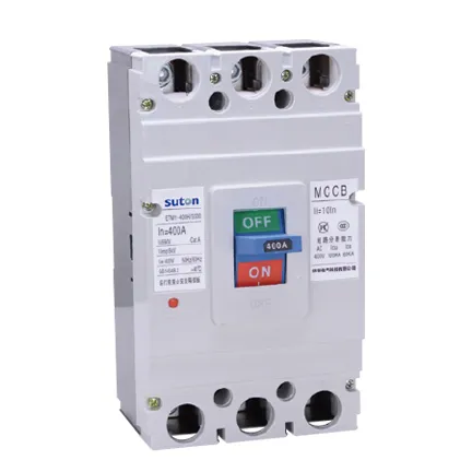
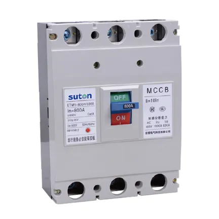
The SUTON ETM1 molded-case circuit breaker range is a relevant product starting point for an MCCB inquiry. The photographs in this article are original images from that product page. They demonstrate product identity, not approval for a particular motor feeder. Provide SUTON with the motor and system schedule and ask for the exact model data, trip characteristic, terminal information, and any applicable starter-coordination evidence. If those documents do not support the proposed duty, select another suitable configuration rather than stretching the product claim.
For a broader review of protective devices before choosing a motor-feeder component, see the circuit breaker types guide. A motor-feeder study remains distinct from a generic feeder or generator application; keep the protection record tied to the actual motor and starter.
Educational video: why motor starting matters
This university lecture from NPTEL IIT Kharagpur introduces starting of three-phase induction motors. It helps explain why a starting-current profile belongs in the breaker review, but does not prescribe a setting for a specific MCCB.

Watch the NPTEL lecture on YouTube.
Frequently asked questions
Can I size an MCCB only from motor full-load current?
No. Full-load current is one input. Starting behavior, conductor protection, available fault current, the overload device, the breaker curve, and local rules must also be checked.
Does an MCCB replace a motor overload relay?
Not automatically. The answer depends on the exact breaker trip unit and the approved starter design. State which component provides each protection function.
What if the breaker trips during a normal start?
Determine the actual trip cause and compare the measured start with the approved curves. Do not simply raise the breaker setting or rating before verifying conductor and fault protection.