


main incomer: A main incomer is the incoming circuit and switching or protective device that connects a switchboard or panel to its supply. Depending on the design, it may provide isolation, overcurrent protection, metering interfaces, remote operation, interlocking, or transfer logic. Selection starts with the system and operating philosophy, not only the continuous-current rating. This guide is written for panel builders, electrical contractors, plant engineers, and technical buyers. It explains the decision and documentation process, not a substitute for project calculations, the adopted rules, manufacturer instructions, or qualified electrical work.
Quick decision table
| Selection input | Question to answer | Required evidence |
|---|---|---|
| Supply | What voltage, frequency, phases, grounding and source arrangement apply? | One-line diagram and utility or transformer data |
| Load | What maximum demand, diversity, future margin and load profile are approved? | Load schedule and design calculations |
| Fault duty | What prospective current can reach the incomer location? | Short-circuit study and assembly rating |
| Operation | Is local, remote, automatic-transfer or interlocked operation required? | Cause-and-effect and control schematic |
| Maintenance | What isolation, withdrawability, test position and service continuity are needed? | Operating and maintenance strategy |
Safety and maintenance context: see the linked OSHA, NIOSH, NFPA, IEC, or U.S. Department of Energy resources in the references section. Exact project and product requirements may be stricter.
Where the incomer sits in the distribution path
The incomer is normally at the supply entrance to a board section. Downstream may be a bus, bus coupler, feeder breakers and branch circuits. A project can have utility and generator incomers, dual-transformer incomers, or multiple incomers linked by bus-tie logic. The word describes the circuit role, not one breaker technology.
At this stage, record assumptions and acceptance criteria before choosing equipment or performing a test. Compare the installed or proposed arrangement with the exact single-line diagram, control schematic, device instructions, protection study, and project specification. Any conflict between those records needs a responsible engineering decision; it should not be resolved by copying a setting or connection from another panel.
Breaker, switch or switch-fuse
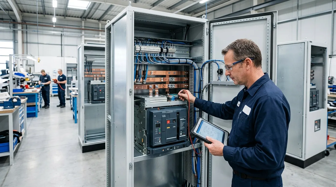
An incomer can use an air circuit breaker, molded-case circuit breaker, switch disconnector, fused switch, or another approved assembly depending on duty. Decide separately which functions are required: automatic fault protection, load switching, isolation, visible status, remote control and maintenance access. Then select a device and assembly that performs them.
At this stage, record assumptions and acceptance criteria before choosing equipment or performing a test. Compare the installed or proposed arrangement with the exact single-line diagram, control schematic, device instructions, protection study, and project specification. Any conflict between those records needs a responsible engineering decision; it should not be resolved by copying a setting or connection from another panel.
Rate the incomer as part of the assembly
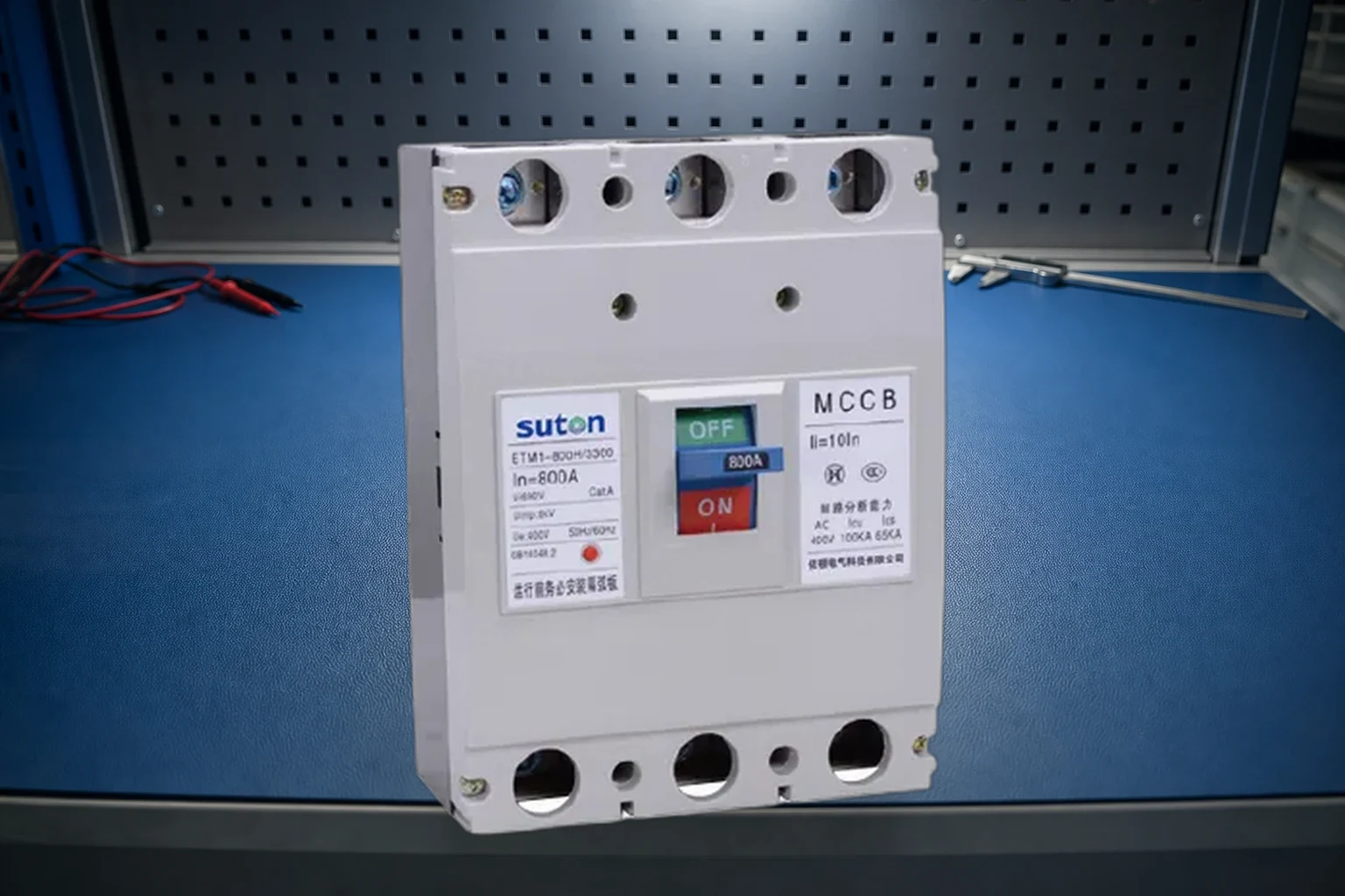
Check rated operational voltage, insulation level, frequency, poles, neutral treatment, continuous current, ambient and enclosure derating, short-circuit withstand and interruption, bus rating, internal separation, terminals, cable or busduct interface, and coordination with upstream and downstream protection. The lowest applicable rating can govern the completed board.
At this stage, record assumptions and acceptance criteria before choosing equipment or performing a test. Compare the installed or proposed arrangement with the exact single-line diagram, control schematic, device instructions, protection study, and project specification. Any conflict between those records needs a responsible engineering decision; it should not be resolved by copying a setting or connection from another panel.
Define operating logic and failure states
For two incomers and a bus coupler, document whether parallel operation is allowed, how interlocks prevent an unsafe state, which source has priority, what happens after undervoltage, and how manual control overrides automatic logic. Status contacts, shunt trips, undervoltage releases and motor operators must match the control voltage and required feedback.
At this stage, record assumptions and acceptance criteria before choosing equipment or performing a test. Compare the installed or proposed arrangement with the exact single-line diagram, control schematic, device instructions, protection study, and project specification. Any conflict between those records needs a responsible engineering decision; it should not be resolved by copying a setting or connection from another panel.
Safety boundary and work control
Electrical equipment can expose people to shock, arc-flash, unexpected motion, stored energy, and loss of critical service. Before inspection or testing, identify every normal, standby, control, and backfeed source. Establish the approved operating condition, interrupt load by the correct sequence, isolate where required, apply the site energy-control procedure, and verify the required condition with appropriately rated equipment. Energized work requires its own justification, qualified people, boundaries, protective equipment, and documented method.
Keep observation separate from intervention. Reading a nameplate, reviewing a curve, or checking a control drawing does not authorize opening energized compartments. Similarly, a remote “open” indication does not prove isolation. The responsible person must define how the circuit will be proven safe and how it will be restored without exposing downstream equipment or personnel to an unexpected state.
Information to collect before selection or testing
Create a single equipment record containing manufacturer, exact catalog number, rated voltage, frequency, current or frame size, poles, breaking or withstand rating, trip-unit or accessory type, settings, control voltage, terminals, conductors, enclosure, environmental conditions, upstream source, downstream load, and adjacent protective devices. Attach the current drawings and note their revision. Similar-looking equipment can have different limits and wiring.
For an existing installation, add as-found photographs, maintenance history, recent trips or alarms, temperature or contamination observations, and any undocumented modifications. For a new panel, add the load schedule, short-circuit study, coordination objective, required spare capacity, communications, metering, interlocks, and contract documentation. Missing inputs should remain visible as open items rather than being replaced with guesses.
Engineering checks that apply to every option
Continuous-current and environmental duty
Confirm normal demand, diversity, continuous operation, cyclic duty, starting or inrush current, harmonics, ambient temperature, altitude, enclosure heat, ventilation, grouping, and terminal limitations. A device rating printed on the front does not by itself prove suitability inside the completed assembly.
Fault duty and coordination
Use the prospective short-circuit current at the actual installation point. Verify the device interruption rating and the assembly short-circuit rating under the specified voltage and conditions. Review upstream and downstream curves, settings, backup or cascading evidence, and the level of selectivity required for service continuity. Do not assume that a higher ampere rating means a higher fault rating.
Mechanical and control integration
Check mounting, bus or conductor interfaces, clearances, barriers, shutters, door interlocks, racking or withdrawable positions, auxiliary contacts, trip and close coils, motor operators, control supply, terminal duty, and communications. Every control signal should have a defined normal state, alarm state, failure response, and test method.
Procurement specification checklist
- System voltage, frequency, phases, grounding and AC or DC duty.
- Normal current, load profile, starting conditions and approved future allowance.
- Prospective fault current, required interruption or withstand duty and coordination objective.
- Exact protective functions, pickup and delay ranges, and who approves settings.
- Poles, neutral arrangement, terminals, conductor material and cable or bus interface.
- Mounting, dimensions, access direction, enclosure and environmental conditions.
- Required auxiliary contacts, releases, control voltage, interlocks, metering and communication.
- Applicable standards, drawings, certificates, routine tests, commissioning records and spare-parts support.
Send this information as a compliance schedule rather than asking only for price and current rating. A supplier response should identify the offered catalog numbers and every deviation. For relevant equipment, review the SUTON product range, then verify the final configuration against the real project inputs.
Commissioning and acceptance record
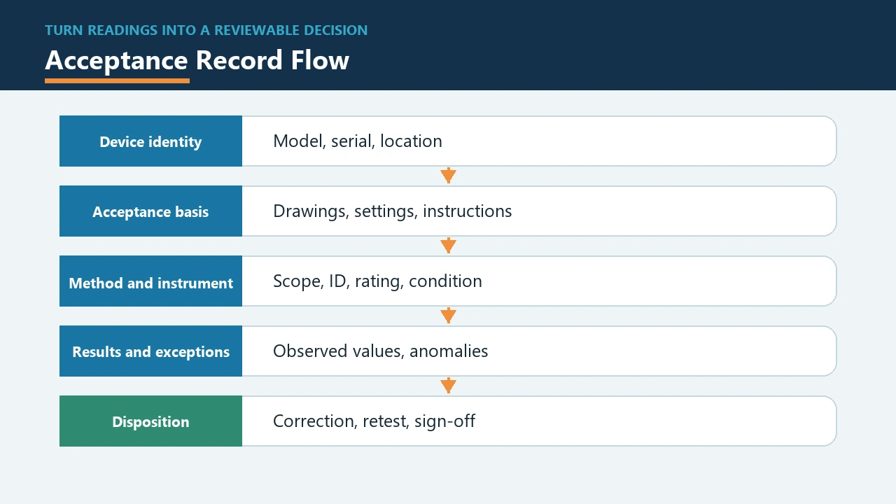
Before energization, confirm identity, ratings, settings, installation, conductor placement, terminal work, mechanical operation, labels, barriers, control wiring, interlocks, and the affected functional tests. Remove temporary grounds, test links, tools, and jumpers. Restore covers and confirm that downstream equipment is ready for the planned energization sequence.
The final record should state who performed and witnessed the work, instrument identification and calibration status, ambient and operating condition, test inputs, measured values with units, acceptance source and revision, result, corrective action, as-left settings, open exceptions, and approval. Separate as-found from as-left conditions. A reviewer should be able to reconstruct why the equipment was accepted without relying on memory.
Common mistakes
- Selecting from the ampere rating alone and ignoring fault duty, curves, accessories, or the completed assembly.
- Using a family brochure instead of the exact catalog number and revision.
- Copying torque, settings, wiring, or test voltage from a different device.
- Changing protection to avoid nuisance operation without investigating the load or fault cause.
- Treating one successful operation as proof of every protective and control function.
- Ignoring upstream sources, generators, photovoltaic systems, UPS equipment, stored energy, or control-power backfeed.
- Failing to update drawings, schedules, labels, maintenance records, and approved spares after a change.
Related guides
- Main circuit breaker guide for panel builders
- Electrical control panel guide for panel builders
- Busbar system guide for panel builders
Authoritative references
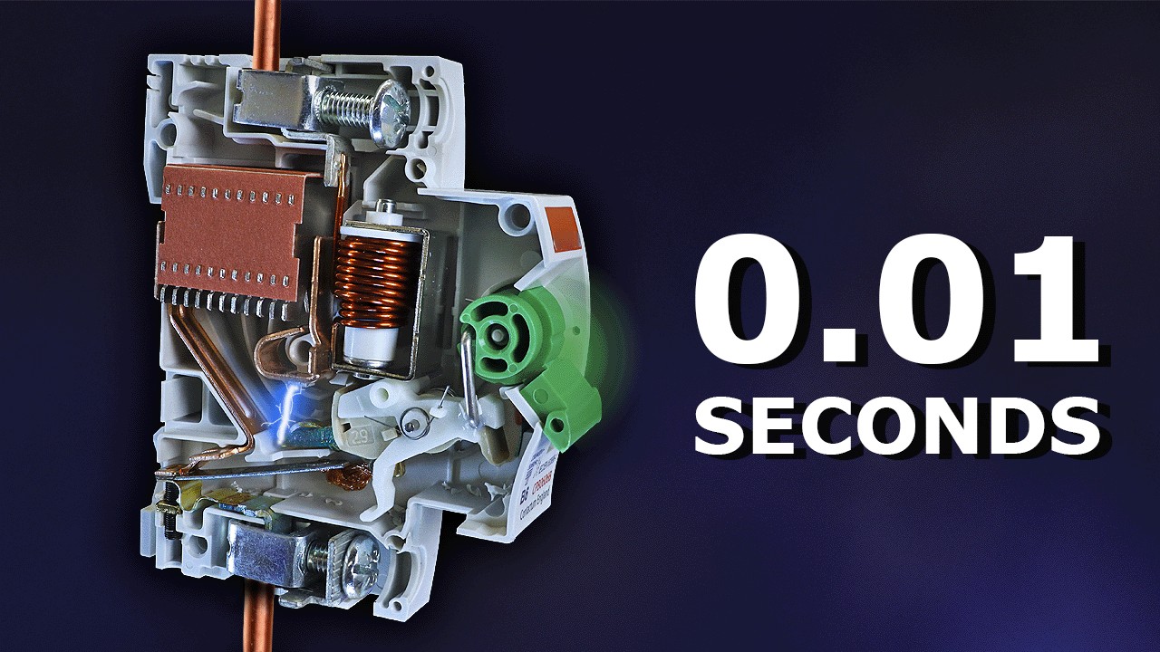
Educational video: circuit breaker fundamentals
This neutral explainer from The Engineering Mindset supports the operating-principle discussion. It does not replace project calculations or product instructions.
Frequently asked questions
Is the main incomer the same as the main breaker?
Sometimes, but not always. Main incomer describes the incoming circuit role; the installed device may be a breaker, switch or another approved arrangement.
How should incomer current be selected?
Use the approved demand, future allowance, conductor and bus ratings, environmental derating and protection study—not a single load total alone.
Why use two incomers and a bus coupler?
The arrangement can improve operational flexibility or continuity, but it requires a defined operating philosophy, interlocks and fault-level review.
Final review
Confirm that the selected equipment or test method matches the actual circuit, approved drawings, protection study, environmental conditions, control philosophy, maintenance plan, and exact manufacturer documentation. Record every unresolved assumption. If the evidence is incomplete, keep the equipment in a safe state and refer the decision to the qualified designer or responsible authority.