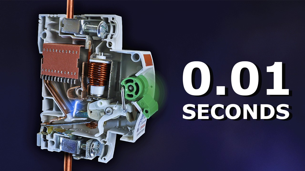
Fuse switch breaker coordination means checking how the upstream fuse and downstream circuit breaker respond to the actual circuit's overcurrent conditions. The aim may be to keep an upstream supply available when the downstream device clears a fault, but that outcome requires device-specific evidence. A larger upstream ampere rating does not prove selectivity. Start with exact fuse and breaker codes, settings, system voltage and the fault assessment, then establish the range over which the required result is supported. Treat the switch-disconnector's switching and isolation duties as separate requirements; they do not establish the protective relationship between the fuse and breaker.
Define the result the project actually needs
Specify which upstream and downstream devices are being compared and which parts of the installation must remain supplied. A general statement that the devices should coordinate is too vague for purchasing or acceptance. Identify whether the requirement covers the evaluated fault range, only a stated range or a particular operating condition. Where the design uses terms such as full or partial selectivity, record the definition and the relevant limit rather than leaving the terms unqualified.
Distinguish selectivity from adequate protection and from backup or cascading arrangements. Two devices can each be suitable protective devices while their combination fails a continuity-of-service requirement. A documented backup combination can improve an accepted protection arrangement without proving that only the downstream device will operate. Keep these decisions separate in the circuit record so one supplier claim is not used to answer a different engineering question.
Collect exact device identities and settings
For the upstream fuse, record the manufacturer, complete part number, current, voltage and application class, together with the applicable characteristic data. For the breaker, record its model, trip-unit version and all relevant settings. A frame designation alone may not identify protective behavior. Include any upstream protective device outside the immediate pair if its operation matters to the project requirement. The accepted relationship should be traceable to the equipment actually installed.
Check the circuit diagram against the intended purchasing list. If the design shows an adjustable breaker but the quote supplies a fixed trip version, the original coordination assessment may no longer apply. Likewise, a substitute fuse can change operating behavior even when its nominal current matches. Treat differences as controlled review items before accepting the equipment, rather than assuming the study covers a broad family of visually similar devices.
Review the operating region before interpreting curves
Time-current data are useful for comparing behavior in the regions they describe. Ensure axes, units, tolerance bands and relevant settings are understood. A single nominal line should not replace the documented operating band. Also account for the relevant load behavior, including starting conditions where these matter. The purpose is to distinguish normal operation, overload response and fault clearing, not merely to draw curves that look separated on a convenient scale.
At high fault currents, published curves alone may not establish the required relationship. Current-limiting behavior, let-through information and supported combination data may be necessary. Do not extend a low-current curve comparison into a universal high-current claim. If the available data stop short of the evaluated condition, identify that gap and request the manufacturer's applicable coordination information or another competent method accepted for the project.
Use coordination evidence for the exact combination
| Coordination input | What to record | What it establishes |
|---|---|---|
| Upstream fuse | Exact code, class and characteristics | Defined protective behavior |
| Downstream breaker | Model, trip unit and settings | Actual configuration assessed |
| Circuit conditions | Voltage and evaluated fault range | Applicable study boundary |
| Supporting data | Specific table or accepted method | Supported result and limits |
| Assembly capability | Approved switch-fuse combination | Separate equipment acceptance |
| Change control | Spare codes and setting authority | When a new review is needed |
The IET discussion of electrical device coordination provides background on discrimination and energy-based comparisons. It should not be converted into a universal ratio or acceptance rule for an upstream fuse and downstream breaker. A method used for one pairing may not establish another. Follow the exact device data and project requirements, and identify the conditions under which the method supports the stated conclusion.
A supplier table is useful only when its scope covers the proposed fuse, breaker, settings and system conditions. Check document revisions and any limitations printed beside the table. If a table names one fuse series, do not silently extend it to a substitute. Keep a copy of the supporting record with the approved parts list so a later maintenance or procurement change can reopen the correct checks.
Establish the evaluated fault range
The prospective fault conditions must come from the installation assessment at the relevant location. Identify both the supply arrangement and changes that could affect it. Alternate supply modes or a modified transformer can change the conditions under which the original relationship was evaluated. Do not assume that a study for one operating configuration covers every future arrangement. Record which supply modes were included and which still require review.
Where the requirement is limited, write the limit clearly in the acceptance file. Avoid a label such as coordinated that hides a boundary important to service continuity. The responsible designer should decide whether the supported range satisfies the project requirement. If it does not, review device selection, settings or the circuit architecture using supported options. Do not reduce necessary protection simply to improve an attractive-looking curve comparison.
Keep fuse-switch assembly ratings in their own review
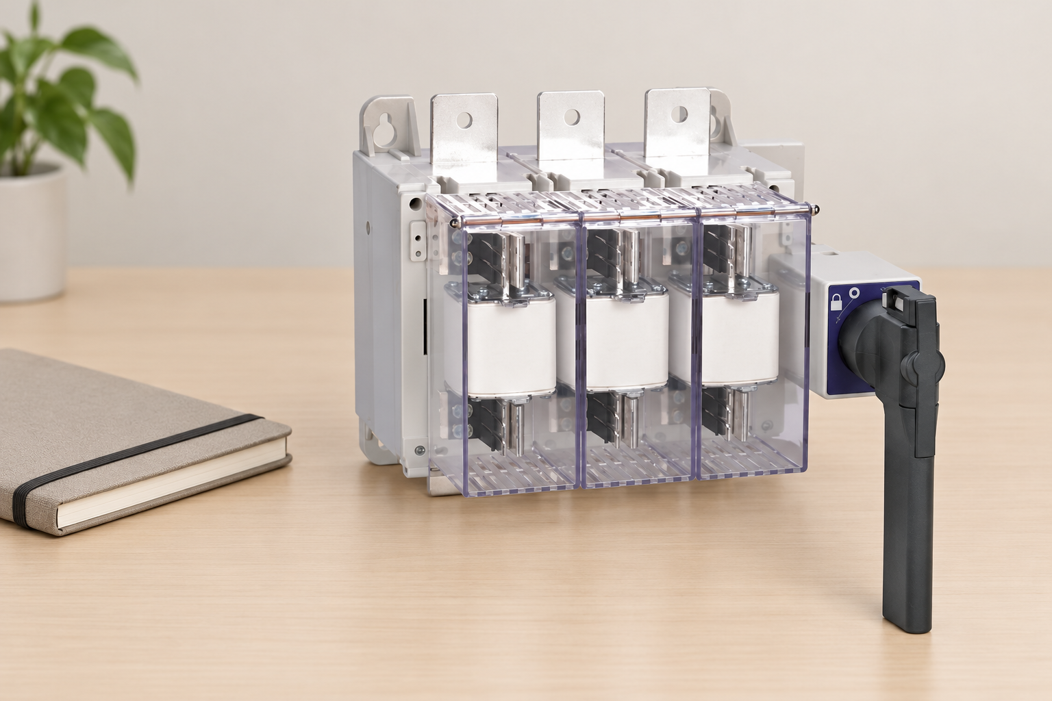
The fuse switch-disconnector must support its assigned load switching, isolation and fault-related conditions as an assembly. The fuse's standalone interruption rating does not approve every holder or switch mechanism beneath it. Ask for the supported fuse combination and installation limits. Review thermal conditions, fuse losses and accessories using the exact equipment documents. These checks remain necessary even when the protective relationship with a downstream breaker has been demonstrated.
The IEC industrial fuse standard scope identifies the publication's industrial fuse subject. Its public listing does not establish a particular pair's selectivity or a SUTON assembly rating. Use AC-22A versus AC-23A switch duty for switching-duty context, and fuse switch-disconnector utilization categories for the load-switching distinction.
Apply the evidence to a SUTON equipment request
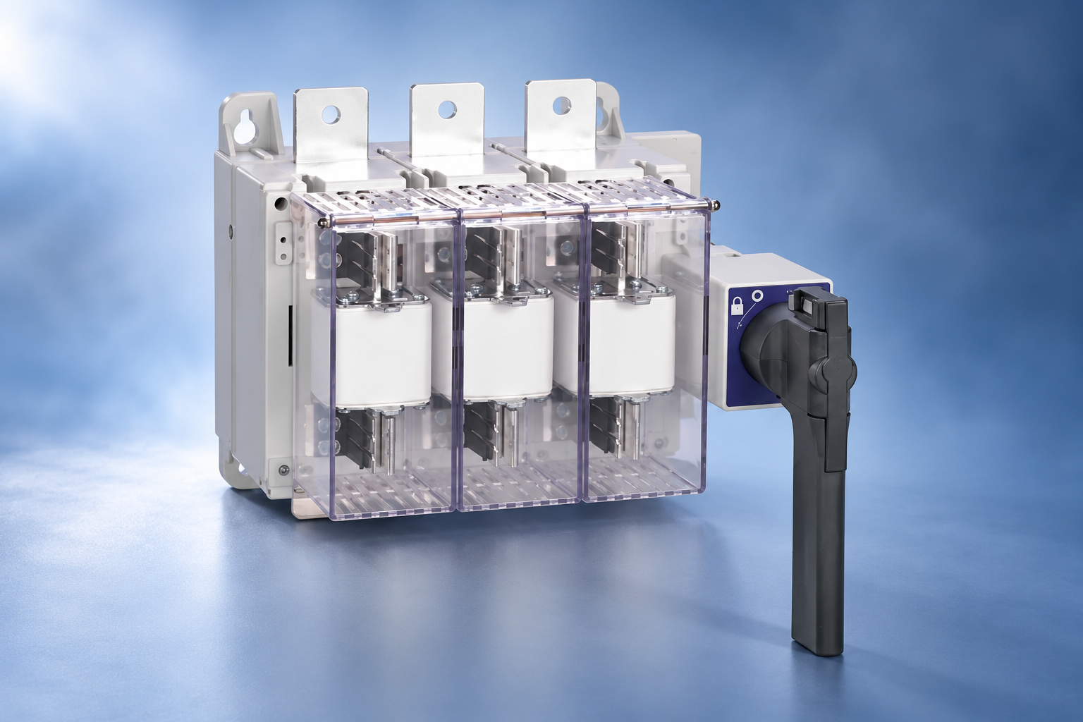
The SUTON ETGLR fuse switch-disconnector page is the physical product reference for this article. Its illustration shows the exterior assembly and fuse positions; it does not depict a tested downstream breaker arrangement. Provide SUTON with the proposed upstream fuse and downstream breaker identities and the circuit requirements. Ask which product and supported fuse combination can be supplied, and which coordination evidence is available for the requested pairing.
If a supplier cannot provide a relevant table, that does not automatically prove failure. It means the required relationship remains unverified by that evidence route. The designer may use another applicable and accepted assessment method, or select a combination with adequate supporting documentation. Record the unresolved question precisely, such as missing high-current data or an uncovered trip-unit setting, instead of labelling the entire product family unsuitable.
Commission and maintain the accepted arrangement
Check the installed product codes and breaker settings against the approved record. A coordination study based on one configuration does not describe a different installed fuse or trip-unit version. Use authorized commissioning and maintenance procedures; do not create an intentional live fault to test an undocumented claim. Any required tests should follow the project acceptance method and equipment instructions, with the responsible people controlling the work.
The HSE switchgear safety guidance gives background for selection, use, care and maintenance. Protection performance is not a substitute for safe isolation. Even a documented coordination result does not mean the upstream terminals are safe when the downstream breaker is open. Alternate sources, stored energy and access conditions still need the site's safe-working process and appropriately authorized personnel.
Control changes that can invalidate the result
Keep the accepted device codes, settings, evidence revision, circuit assumptions and supported fault range in one handover record. Identify who can approve a substitution or setting change. Do not permit a spare description that contains only ampere rating to override the specific fuse used in the assessment. When a substitute is proposed, revisit its behavior and the supported combination before carrying over the original coordination conclusion.
Changes to supply conditions or downstream equipment may also require review. A new branch circuit, different breaker or adjusted trip setting can affect the intended continuity-of-service result. Track these changes as part of ordinary installation records. For a product enquiry, contact SUTON with the exact combination and unresolved evidence item, while keeping circuit-level acceptance with the responsible designer rather than treating a general quotation as a complete study.
For the overall equipment review, use the disconnect-switch guide for panel builders as the parent selection framework. Apply this article to its specific downstream coordination evidence requirements.
Frequently asked questions
Is a larger upstream fuse automatically selective with a smaller breaker?
No. Nominal current alone does not establish the protective relationship. Check the exact fuse characteristic, breaker model and settings, system conditions and evaluated fault range. Relevant combination data or an accepted assessment must support the project's selectivity requirement, including any stated limits that affect continuity of supply.
Can time-current curves prove coordination for every fault current?
Not automatically. Curves are useful within their documented scope, but high-current behavior can require additional let-through or combination evidence. Do not extrapolate a low-current comparison into an unlimited selectivity claim. Identify the range actually supported and have the responsible designer compare it with the installation's required fault conditions.
Does changing the fuse brand preserve the coordination study?
Only if the reviewed evidence and method cover the replacement. The same nominal size and current do not establish identical characteristics, losses or supported combinations. Record the complete approved fuse code and recheck affected protection and coordination decisions before accepting a substitute or treating it as an approved maintenance spare.
Educational video
Why Circuit Breakers DON'T Protect People (electric shocks) by The Engineering Mindset. This video explains electrical-shock protection limits; it supports the safety-function distinction here, not an exact SUTON rating, PV connection, fuse selection or installation procedure.