


A type 1 surge protector is the permanently connected SPD class specified for the service entrance: it can be installed on the line side of the service overcurrent device, and listed Type 1 devices are also commonly applied on the load side. In plain terms, it is the origin-stage surge module you place where utility energy enters the premises board—not a random DIN-rail accessory and not a substitute for the main breaker.
This guide stays on Type 1 / service-entrance selection and the panel inputs that lock that decision. It contrasts Type 2 only where location and disconnect rules change the order, then points to SUTON’s ETU1 documentation path. Coordination details that mix SPD duty with breaker backup already live in SUTON’s surge-protector-breaker and circuit-breaker-surge-protector guides; those pages are linked rather than rewritten here.
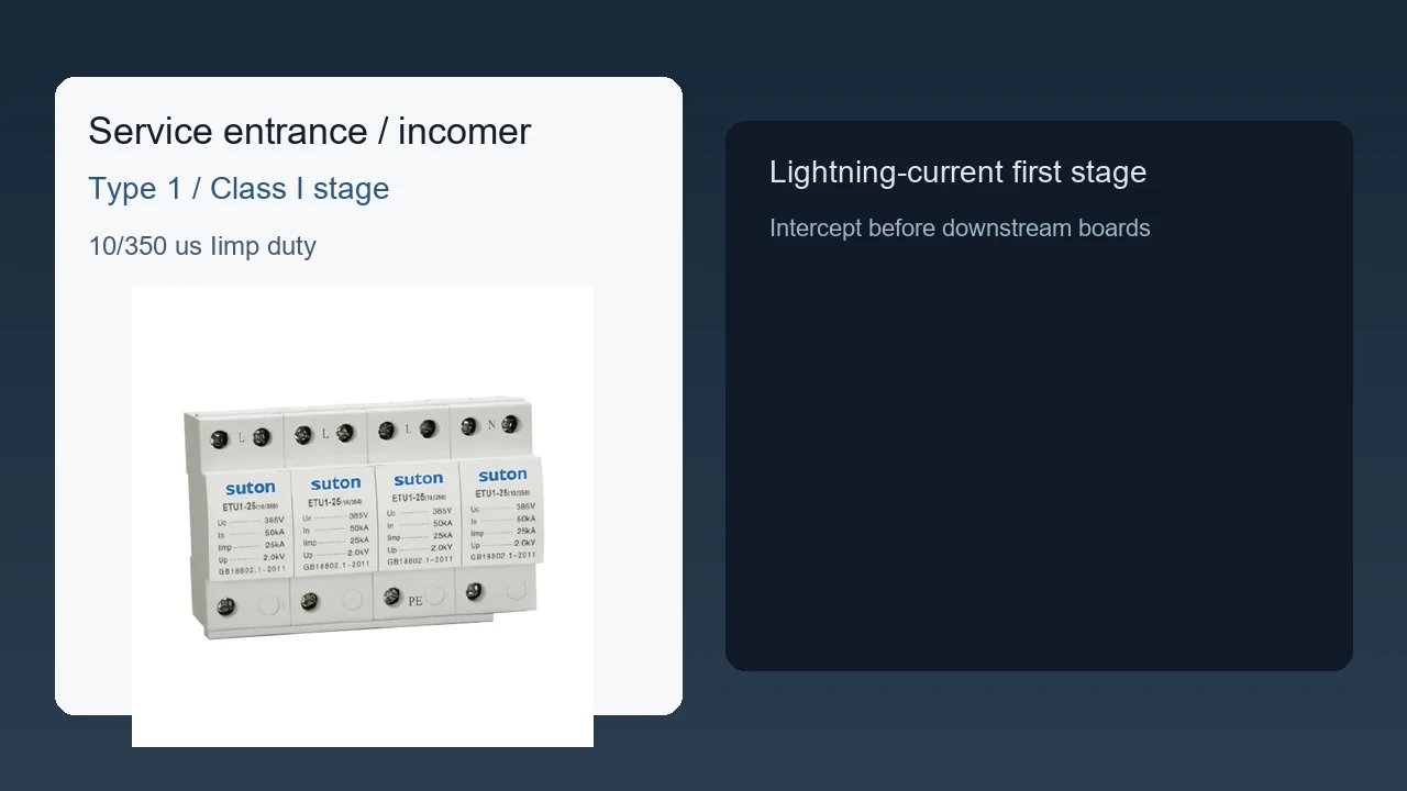
What a Type 1 Surge Protector Does at the Service Entrance
A Type 1 surge protective device is a hard-wired SPD intended for the service equipment zone—between the secondary of the utility service transformer and the line side of the service overcurrent protective device, and also on the load side when the listing allows it. Professionally, that location class is what “Type 1” names under UL 1449 / NEC Article 242 practice. In everyday panel language, it is the first surge stage at the incomer.
The device limits transient overvoltage and diverts surge energy on the assigned conductors. It does not provide overload or short-circuit interruption the way an MCB or MCCB does. When a buyer asks for a type 1 surge protection device on a main board, the useful reply starts with the single-line location, not with a catalogue photograph alone.
On projects that follow NEC 230.67 for covered dwelling or related occupancies, the required SPD type is Type 1 or Type 2, located in or immediately adjacent to the service equipment. That code trigger explains why Type 1 language appears so often on service replacements; it does not by itself pick poles, voltage, or impulse grade for an IEC drawing.
Type 1 vs Type 2: Location and Disconnect Rules
Type 1 and Type 2 are location classes relative to the service disconnect, not marketing synonyms for “strong” and “weak.” Type 1 may be connected on the supply side of the service disconnect where permitted, or under Type 2 connection rules; Type 2 stays on the load side of that overcurrent device.
| Decision | Type 1 SPD | Type 2 SPD |
|---|---|---|
| Typical zone | Service entrance / origin | Load side of service OCPD; distribution boards |
| Line side of service disconnect | Permitted when listed as Type 1 | Not the Type 2 location class |
| Dedicated breaker / disconnect | Often not required by Type listing; still follow the datasheet | Commonly connected through a breaker, switch, or listed arrangement |
| Dual use | Frequently dual-rated for Type 2 applications | Remains a load-side device class |
Electricians on the trade forums repeatedly treat Type 1 as the option when a dedicated breaker space is unavailable, while still checking lug ratings and manufacturer instructions. That field habit matches the listing idea, but it is not a license to ignore the selected product’s installation sheet.
Important: Install the Type 1 unit only in the orientation and connection method the listing and instructions allow. A meter-side or lug landing that voids the listing can also void warranty expectations when a surge claim is reviewed. Source: Electrician Talk — Type 1 placement discussion.
If the immediate need is how an SPD shares a board with a backup breaker or fuse, use the surge protector breaker guide rather than stretching this Type 1 page into that coordination job.
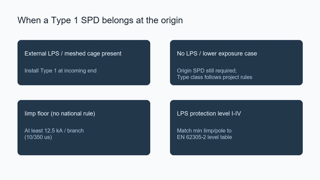
When Iimp (10/350) Marks Type 1 / Class I Impulse Duty
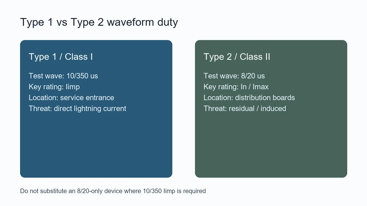
On IEC-oriented drawings, the origin stage is often written as Class I SPD / Type 1 duty with an Iimp surge rating on the 10/350 µs wave. That number is the professional check for lightning-current capability at the installation origin. In plain language, it is the high-energy surge figure you verify before you accept an 8/20-only module as an origin device.
Type 2 / Class II language usually centers on In or Imax on the 8/20 µs wave for residual or induced threats at distribution boards. Substituting an 8/20-only device where the single-line calls for 10/350 Iimp changes the documented duty even if the DIN-rail width looks identical.
SUTON’s published ETU1 family table lists Iimp (10/350 µs) grades of 12.5, 15, 25, and 50 kA with Up <2.5 kV. Those figures are documentation cues for an inquiry—they are not a claim that every project must use one specific grade, and they are not a substitute for confirming the exact marking on the offered device.
IEC 61643-11 frames SPD requirements and test methods for low-voltage power SPDs; IEC 61643-12 covers selection, location, and coordination principles. Use those scopes to keep the drawing language aligned with the product test class you are buying.
Panel Inputs That Lock a Type 1 Specification
A Type 1 order fails when the quotation only repeats the keyword. Lock the following inputs on the controlled documents before comparing suppliers.
| Panel input | Why it locks Type 1 selection | Send with the inquiry |
|---|---|---|
| Supply system, voltage, earthing arrangement | Fixes poles, Uc, and connection concept | Yes |
| Origin location on the single-line (line side / load side of service OCPD) | Confirms Type 1 location class vs Type 2-only placement | Yes |
| Required marking language (UL Type 1 and/or IEC Class I / Iimp) | Prevents 8/20-only substitutions at the origin | Yes |
| Iimp grade or project impulse requirement when stated | Selects among published 10/350 grades | When the drawing states it |
| Manufacturer backup / disconnect instructions | May still require a specific OCPD arrangement | Yes |
| Prospective fault context at the SPD terminals | Supports SCCR / backup review | Yes |
| Conductor route, length limits, and PE bonding path | Controls effective let-through in the enclosure | Yes |
| Poles, module width, and enclosure interface | Fixes physical fit on the incomer rail | Yes |
| Environment and standards requested | Fixes approval pack expectations | Yes |
Scenario: a panel shop receives “Type 1 SPD, 4P” with no earthing arrangement and no note on line-side versus load-side landing. Two vendors can both ship modular SPDs and still miss the origin duty the EPC intended. The table above is the minimum package that makes those quotations comparable.
For mixed “circuit breaker surge protector” RFQs that still confuse SPD role with upstream protective-device role, hand the buyer the circuit breaker surge protector guide after the Type 1 location is marked on the drawing.
Incomer Placement, Short Leads, and Bonding
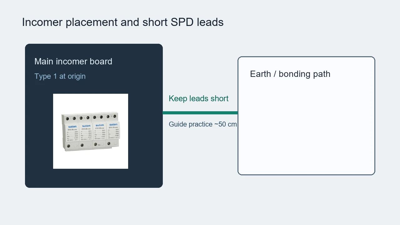
Place the Type 1 module where the approved single-line shows the origin / incomer stage—typically the main incomer board or service equipment zone—not wherever empty rail space happens to exist. The surge path is parallel: the device clamps when voltage rises, so long, coiled leads raise impedance and increase the voltage that appears at the protected bus.
Keep the line, neutral, and PE conductors as short and direct as the enclosure and listing allow. Trade discussions on Type 1 placement repeatedly return to the same practical point: lead length and listing-compliant landing matter more than treating the SPD as a series filter that “blocks” everything upstream of the meter.
Confirm terminal capacity, multi-wire lug ratings, and torque or inspection steps from the product instructions before energization. A Type 1 listing that allows installation without a dedicated breaker still does not authorize an unlisted double-tap on a lug that is not rated for multiple conductors.
Keep Type 1 as the Origin Stage, Not the Whole Cascade
Type 1 at the service entrance is the first stage against high-energy external events. It does not automatically finish protection for every feeder panel or sensitive load. Residual or internally generated transients are why designs often add Type 2 stages downstream and, where needed, point-of-use devices closer to equipment.
Keep those stages as separate lines on the bill of materials. Swapping a Type 1 origin device for a Type 2-only module—or deleting downstream stages because “Type 1 is installed”—changes the documented cascade even when the incomer rail still looks populated.
This page stops at that boundary on purpose. If the open question is how the SPD shares backup or disconnect duty with a breaker on the same assembly, return to the surge-protector-breaker guide instead of expanding Type 1 selection into a full coordination study.
Select SUTON ETU1 Product Documentation for Type 1 / Iimp Grades
After the single-line shows a Type 1 / origin impulse requirement, open SUTON’s ETU1 series surge protective device page as the modular documentation path. The published family lists Iimp (10/350 µs) grades of 12.5, 15, 25, and 50 kA, Up <2.5 kV, IP20 indoor modular construction, and pole options including 1P, 2P, 1P+N, 3P, 4P, and 3P+N.
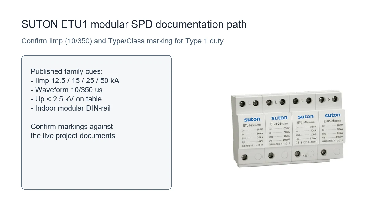
Read the live table for Up / Uc / In markings: continuous operating voltage (Uc), voltage protection level Up, and nominal discharge current In where listed, published upstream circuit-breaker values by grade, wire capacity, and the standards list on the page. Confirm the offered marking against the project’s Type/Class language before treating any single grade as released for that board.
Browse the Modular DIN Rail Products hub for related modular families, then contact SUTON with the single-line, earthing arrangement, Type 1 location note, and required documents. Public pages support the documentation route; they do not approve a specific panel arrangement by themselves.
FAQ
What is a Type 1 surge protector?
It is a permanently connected SPD intended for the service entrance zone, including installation on the line side of the service overcurrent device when listed as Type 1, and commonly also usable on the load side.
How do Type 1 SPDs differ from Type 2?
Type 1 is the location class that can sit on the line side of the service disconnect; Type 2 is intended for the load side. Dual-rated Type 1 devices are often also usable in Type 2 applications.
Does a Type 1 SPD always need a breaker?
Type 1 listing often allows installation without a dedicated external breaker, but the selected product instructions, lug ratings, and project rules still control the final arrangement.
Where should a Type 1 surge protective device be installed?
On the approved single-line at the service equipment / origin—line side where permitted, or load side when that is the listed and designed landing—keeping conductors short.
What does Iimp (10/350) mean for Type 1 duty?
It is the impulse current rating on the 10/350 µs wave used to document Class I / Type 1 lightning-current capability at the origin. Do not assume an 8/20-only In rating covers that duty.
Which panel inputs should go with a Type 1 inquiry?
System voltage and earthing, origin location relative to the service OCPD, required Type/Class or Iimp marking, poles, backup instructions, fault context, conductor constraints, and standards requested.
Does installing Type 1 remove the need for Type 2 downstream?
No. Type 1 is the origin stage. Residual Type 2 or equipment-level stages remain separate design decisions when the protection concept requires them.
Which SUTON family documents Type 1 / Iimp grades?
The ETU1 series publishes Iimp (10/350 µs) grades on its product page under Modular DIN Rail Products; confirm the offered marking against the project documents before purchase.