


A motor control center is an assembly decision — not a cabinet outline with starters. Panel builders use the term when a motor schedule, control narrative, and single-line diagram must be translated into coordinated feeders, buckets, control power, and maintenance interfaces.
Start with the approved motor list and one-line diagram. Record feeder duty, start methods, isolation requirements, fault duty, and control philosophy before any bucket quotation is compared.
Important: This guide structures motor control center specification for low-voltage assemblies in line with IEC 61439-1 and motor-control product scope in IEC 60947-4-1. It cannot approve protection settings, bucket interchangeability, or control logic where motor data, fault duty, or the approved sequence is missing — hold those inputs for engineering review before manufacture.
Part 1. Turn an MCC request into documented assembly inputs
Ask “which MCC for this project?” and you are asking for a controlled input set tied to a motor schedule and assembly boundary. A motor control center groups motor feeders, control functions, power distribution, and operating interfaces into a coordinated structure. A cabinet outline or a list of starters alone does not define an MCC.
| Selection factor | Why it matters for the assembly | Send with quote |
|---|---|---|
| Motor schedule with duty and start method | fixes feeder protective and control duty | yes |
| Single-line diagram and source arrangement | fixes busbar and fault-duty context | yes |
| Isolation requirement per feeder | fixes bucket and disconnect arrangement | yes |
| Control voltage, interlocks, and communications | fixes terminal and wireway scope | yes |
| Prospective fault duty at the assembly | supports protective coordination review | yes |
| Enclosure environment and cable entries | fixes physical interface | yes |
| Standards requested and feeder quantities | fixes approval and procurement batch | yes |
Projects that skip the table often receive quotations built on starter count alone. That produces a second procurement cycle once control logic, bucket interfaces, or maintainability scope is challenged on site.
Part 2. Separate MCC scope from standalone starter panels
An MCC is a coordinated assembly of multiple motor feeders with defined power, control, isolation, and maintenance interfaces. A standalone motor starter panel may serve one or a few circuits, but it does not automatically carry the same bucket, busbar, and control-power architecture as a full MCC.
| Assembly scope | Primary planning focus | Common mistake |
|---|---|---|
| Full MCC | Multi-feeder coordination, busbar duty, bucket interfaces | Treating it as a larger starter panel |
| Motor starter panel | Defined motor branch control and protection | Omitting assembly-level control power planning |
| Distribution plus MCC section | Incoming and outgoing boundary clarity | Mixing feeder roles without a schedule |
| Retrofit into existing MCC | Mechanical and busbar compatibility | Assuming interchangeable buckets by rating alone |
Motor-starter and branch-protection context lives in the motor starter guide and the circuit breaker guide. This article owns MCC assembly inputs, feeder interfaces, and RFQ structure only.
Part 3. Record motor schedule and feeder inputs
Use the motor list, load list, control narrative, single-line diagram, and site conditions together. For each feeder, identify motor duty, starting method, isolation requirement, protection function, control voltage, interlocks, and communications.
Record prospective fault duty and source arrangements at the assembly location. A bucket or compartment must be reviewed as a power, control, and mechanical interface — confirm incoming and outgoing terminations, busbar access, withdrawable or fixed arrangement, isolation sequence, and labelling.
Do not assume devices with similar ratings share the same physical or control interface. Late discovery of a bucket mismatch often forces a layout rebuild after procurement has started.
Part 4. Review bucket interfaces and control power
Control circuits carry the start, stop, permissive, alarm, and remote-control logic that makes a motor feeder usable. Document control voltage, fusing, terminal allocation, interlocking, emergency-stop interface, and the hand-off-auto philosophy.
| Interface check | Why it matters |
|---|---|
| Bucket mechanical and busbar fit | fixes whether the feeder can be built as drawn |
| Control terminal allocation | fixes wireway and auxiliary scope |
| Interlock and permissive list | fixes sequence testing |
| Maintenance access and isolation sequence | fixes serviceability |
| Device marking versus schedule | fixes commissioning traceability |
A late control change can alter wireways, terminal count, and test scope even when motor duty appears unchanged. Treat control-narrative revisions as controlled events and update the schedule before release.
Part 5. Verify commissioning and maintainability requirements
Provide clear feeder identification, accessible terminals, approved isolation points, and records that connect each bucket to its motor and control narrative. Commission against the approved test method and capture the source state, rotation check, and functional interlock results.
Before handover, reconcile the installed assembly with the approved design. Include the motor schedule, device schedule, wiring diagram, installation instructions, inspection outcomes, and test evidence in the project file.
Field modifications need controlled drawing updates. An added motor, changed start method, or swapped protective device alters coordination and commissioning scope even when nominal ratings appear unchanged.
Part 6. Route an evidence-based SUTON inquiry
Send with the inquiry:
| RFQ input | Why it matters |
|---|---|
| Single-line diagram and motor schedule | fixes feeder scope and source context |
| Start methods, isolation, and protection functions | fixes bucket content |
| Fault-study reference and busbar duty | supports coordination review |
| Control philosophy, interlocks, and communications | fixes control scope |
| Enclosure environment, cable entries, and mounting | fixes physical interface |
| Standards requested, accessories, and quantities | fixes approval and procurement batch |
Require suppliers to declare the exact offered arrangement, installation instructions, accessories, and exceptions against the controlled documents. Hold the engineering decision when motor duty, bucket interface, or control logic is incomplete — a quotation against an undefined schedule cannot preserve the design intent.
Fit Boundary: this guide organizes MCC assembly inputs for panel builders. It does not approve protection settings, does not guarantee interchangeability between existing bucket systems, and cannot finalize an assembly where motor data, fault duty, or control logic is missing. Escalate those gaps to the design authority before the package is priced.
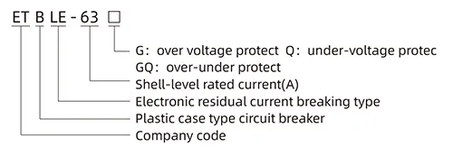
SUTON’s modular DIN rail products provide a public route for relevant modular control-panel categories. For a project review, send the motor schedule, one-line diagram, and control narrative through Contact SUTON. Require each MCC quotation to cite the same motor schedule and keep the approved feeder list with the assembly record.
MCC dossier and service discipline
Treat the motor schedule, control narrative, bucket interface records, test results, and revision history as one handover package. Facilities that inherit the dossier can maintain and expand the MCC with traceability; facilities that inherit only a cabinet label tend to rebuild the review from scratch at the first trip or modification event.
After any unexplained feeder trip, record the motor state, configured settings, connected load, and recent switching activity before reset. Patterns across records often distinguish a setting issue from a control-logic gap the original specification did not capture.
When feeders are added or rearranged, revise the schedule and one-line diagram before re-energizing. A new motor or changed start method alters coordination and commissioning scope even when the bucket rating appears unchanged.
FAQ
What is a motor control center?
It is a coordinated assembly of motor feeders, control functions, and power distribution built from a documented motor schedule and single-line diagram.
Is an MCC just a panel with starters?
No. It also requires defined power, control, isolation, maintenance, and test interfaces at assembly level.
What defines an MCC feeder?
Motor duty, start method, protection function, control voltage, terminations, interlocks, and fault duty define the feeder.
Why is the control narrative needed?
It defines operating logic and interlocks that affect wiring, terminals, testing, and maintenance.
Can existing buckets be treated as interchangeable?
No. Verify their mechanical, busbar, power, and control interfaces against the authorized assembly documentation.
What should an MCC RFQ include?
Include the motor schedule, single-line diagram, fault duty, control philosophy, environment, standards, entries, and quantities.