


mcb vs mccb is a design decision, not a label comparison. An MCB is normally chosen as a compact, standardized branch protective device. An MCCB is selected when the project needs a molded-case platform, a broader engineered duty, or adjustable trip functions. The decisive question is not which acronym is ‘better’; it is which device has verified ratings and characteristics for the conductor, load, available fault current, installation standard, and coordination study. For a safe procurement decision, define the circuit role first, then verify voltage, continuous current, available fault current, trip behavior, coordination, installation method, and the applicable standard. The final selection must be approved by the responsible qualified designer for the actual project.
Quick answer: how MCB and MCCB differ
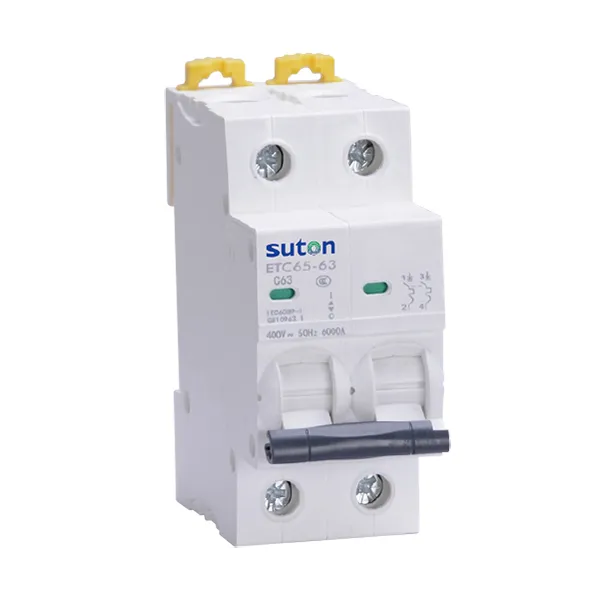
Use MCB when the required role is final branch circuits and compact modular distribution. Use MCCB when the required role is feeders, larger loads, incomers, and duties that may require adjustable protection. That statement is a starting point, not a substitution rule. Product families overlap, regional terminology differs, and the exact offered model may have options that a generic comparison cannot capture.
| Decision point | MCB | MCCB |
|---|---|---|
| Typical panel role | Outgoing branch way | Feeder, submain, large load, or incomer |
| Trip settings | Usually fixed by product design | May be fixed or adjustable; verify the exact trip unit |
| Space and mounting | Compact modular format is common | Larger molded-case format; mounting varies |
| Engineering evidence | Device curve and declared ratings | Declared ratings, trip-unit settings, coordination and accessory data |
| Procurement risk | Assuming all MCBs with the same current rating are interchangeable | Assuming frame size, trip rating, and interrupting duty mean the same thing |
Basis: project design inputs and the declared scope of IEC 60898-1 and IEC 60947-2. Always use the edition and local adoption specified by the project.
Start with the circuit function, not the enclosure
Write a one-sentence duty statement before comparing catalog pages: identify the source, the protected conductor or equipment, the load, normal operating current, switching duty, and the consequence of a trip. This prevents a common error—choosing a familiar device shape and trying to make the study fit afterward. Two products may look similar while having different standards, terminals, trip systems, environmental limits, or short-circuit ratings.
The single-line diagram should show where the device sits in relation to the source and downstream circuits. The schedule should identify poles, neutral treatment, rated voltage, rated current, frequency where applicable, trip function, and accessories. If the device supports isolation or remote operation, state that duty separately; protection, switching, and isolation are related but not automatically identical functions.
Check load current and conductor protection separately
A breaker is not selected simply by matching its printed ampere value to a calculated load. The designer must consider conductor ampacity under the real installation method, ambient conditions, grouping, duty cycle, starting or inrush behavior, and the load’s own protection requirements. The protective setting or characteristic must protect the conductor while allowing normal operation. Adjustable settings are useful only when they are calculated, recorded, secured, and commissioned.
Do not assume that increasing a breaker rating solves nuisance tripping. A trip can indicate overload, short circuit, earth leakage, inrush, a wiring defect, an unsuitable curve, or a coordination problem. Identify the trip function and cause before changing the device. The circuit breaker trip guide explains how to separate these questions.
Verify voltage and fault-interruption duty
The available fault current must be calculated or obtained for the exact installation point. Compare it with the manufacturer-declared interrupting or short-circuit capacity at the actual voltage and system arrangement. OSHA’s general electrical requirements state that equipment intended to interrupt fault current must have an interrupting rating sufficient for the nominal voltage and the available current at its line terminals.
Keep continuous-current rating and breaking capacity separate in the approval record. Also distinguish values defined by different standards, such as service and ultimate short-circuit capacities or domestic-device short-circuit capacity. Similar numbers are not automatically equivalent. If backup or cascading protection is proposed, require tested or otherwise accepted manufacturer evidence for the exact upstream and downstream combination.
Compare trip behavior across the full operating range
Protection must work from modest overloads through high-current faults. Review the complete time-current characteristic, including tolerance bands and instantaneous regions. For electronic trip units, record every setting and verify that the chosen values match the coordination study. For fixed devices, confirm that the published characteristic is appropriate for the conductor and load rather than relying on a curve letter or marketing name alone.
Coordination has two goals that can conflict: clear faults fast enough to limit damage, and preserve supply to healthy circuits where the project requires continuity. State the priority for each feeder. A hospital essential system, continuous process line, office distribution board, and small machine panel can require different operating objectives even when nominal current values look similar.
Plan installation, operation, and maintenance
Confirm terminal type and conductor range, tightening method, heat dissipation, enclosure spacing, mounting orientation, environmental conditions, accessibility, and permitted accessories. Do not copy torque values or clearances from another frame size. Use the instructions supplied for the exact model. Panel builders should also verify door interlocks, external handles, auxiliary contacts, shunt trips, undervoltage releases, motor operators, and communication modules when those functions are required.
Maintenance strategy matters at the selection stage. Decide whether the device is expected to be inspected, tested, adjusted, withdrawn, or replaced as a unit. Identify spare-parts policy and the records needed after a trip. A breaker that clears a severe fault should not simply be reclosed without the inspection and fault-investigation steps required by the manufacturer and site safety procedure.
A repeatable selection workflow
- Define the circuit: source, system voltage, earthing arrangement, load, conductor, duty, and required poles.
- Calculate normal duty: design current, inrush or starting behavior, installation derating, and conductor capacity.
- Calculate fault duty: maximum and minimum prospective fault current at the device location.
- Select the protection function: overload, short circuit, residual current, isolation, and control requirements.
- Check coordination: curves, settings, selectivity objective, and any manufacturer combination tables.
- Check the panel: assembly rating, terminals, temperature rise, spacing, access, accessories, and labeling.
- Approve exact evidence: model code, datasheet revision, certificates required by the contract, drawings, and settings.
- Commission: visual checks, mechanical operation, setting verification, required tests, and signed records.
What to include in an RFQ or technical submittal
Give suppliers enough information to offer one clearly defined device rather than a family brochure. Include system voltage and frequency, AC or DC duty, poles and neutral arrangement, continuous current, calculated fault current, required breaking capacity under the named standard, trip functions and settings, utilization duty, installation form, terminal and cable details, accessories, control voltage, communication needs, ambient and enclosure conditions, certification requirements, and the required drawing and test-document package.
Request a completed compliance schedule that points to the exact evidence for each requirement. Record exceptions explicitly. A model code without a decoded option list is not enough when trip units, accessories, terminal kits, or breaking capacities vary within the same family. For SUTON equipment, begin with the modular DIN-rail breaker range and request confirmation for the actual project conditions.
Safety boundary for selection and testing
This guide supports specification work; it is not an energized-work procedure. Fault studies, protection settings, installation, and commissioning must be performed or approved by qualified people under the applicable local rules. OSHA 1910.333 requires live parts to be de-energized before work unless specific exceptions apply and sets requirements for safe de-energizing. Follow the project’s lockout, verification, personal protective equipment, and arc-flash procedures.
Related SUTON planning resources
Use the circuit breaker types guide as the parent overview, then continue with these complementary pages:
Educational video: breaker and current fundamentals
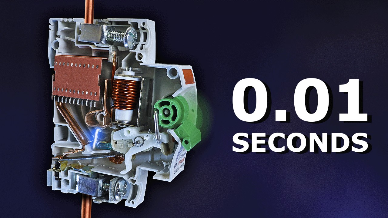
The following neutral educational video from The Engineering Mindset supports the operating-principle section. It does not replace project calculations or manufacturer instructions.
Watch Why Circuit Breakers Don't Protect People on YouTube.
Frequently asked questions
Can an MCCB replace an MCB?
Only after the complete application is checked. Physical fit, conductor protection, trip behavior, fault duty, coordination, isolation, and applicable rules all matter.
Is an MCCB always adjustable?
No. Adjustment depends on the exact trip unit and product configuration. Request the manufacturer’s data for the offered device.
Which device should be used for a branch circuit?
Use the device type and ratings accepted by the project design and installation rules. Compact MCBs are common, but the answer must follow the actual circuit study.
Conclusion
The practical answer to mcb vs mccb comes from the circuit study and operating objective. Define the role, compare verified ratings at the real voltage and fault level, review the full trip behavior, check installation and maintenance constraints, and approve the exact offered configuration. That process creates a defensible panel schedule and reduces the risk of substitutions based only on current rating, enclosure size, or acronym.