


An auxiliary switch gives a control or indication circuit a defined change of state from a host breaker or switch assembly. Before procurement, the panel team needs the host device, the required state, the control interface, and the released accessory evidence—not just an accessory label.
Important: IEC 60947-2 addresses low-voltage circuit-breaker product scope, but a panel drawing and the exact host-device documentation still govern accessory selection and verification. An auxiliary switch is not a substitute for protective coordination or a safety-function decision.
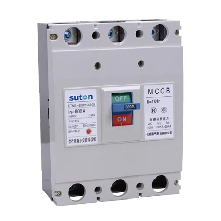
Part 1. Auxiliary-switch role and boundary
An auxiliary switch is an accessory interface associated with a host device. It transfers a documented state to a separate circuit for indication, monitoring, interlocking, or another approved control purpose. The host breaker retains its own protective role; the auxiliary switch does not add overcurrent protection.
The auxiliary contact guide explains the compact breaker status-contact route. This page focuses on the broader procurement record for an auxiliary-switch request. A shunt trip guide is the adjacent article when the design needs a remote opening command rather than state feedback.
Part 2. Host-breaker identity and compatibility evidence
Start with the exact host series, frame, poles, operating arrangement, and current schedule reference. Then collect the accessory code, mounting side or slot, permitted combinations, terminal illustration, and any special ordering notation from the selected family’s documentation. Compatibility belongs to the relationship between those items; it cannot be established from the phrase “auxiliary switch.”
The public ETM1 molded case circuit breaker page lists auxiliary contacts among its orderable accessories and asks customers to specify included accessories. That is a valid family-level starting point, not proof that every ETM1 configuration accepts the same accessory.
| Evidence item | Why it matters | Record for the panel file |
|---|---|---|
| Host model and frame | identifies the accessory family | schedule reference and model string |
| Pole and operating arrangement | can affect mechanical configuration | single-line and GA reference |
| Accessory code and position | controls the correct interface | released catalogue page or drawing |
| Contact logic and terminal marking | defines the receiving circuit | control schematic |
| Combination restrictions | prevents incompatible attachments | manufacturer instruction revision |
Part 3. Control logic and signal definition
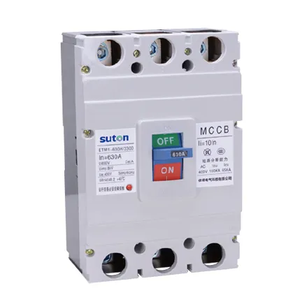
Write the normal state, the event that changes it, the signal destination, and the expected indication on the control drawing. NO and NC describe contact logic in that documented circuit; they do not create a universal terminal assignment for every accessory family. The released marking remains the source for the selected device.
Keep state feedback separate from an opening command, alarm output, or protective trip function. A drawing can include more than one accessory only when the host documentation and project logic support the combination. The circuit breaker guide gives the wider device boundary for this review.
Part 4. Mounting, wiring and commissioning records
Layout review should reserve the accessory location, wiring route, terminal space, labels, and access needed for inspection. The panel GA and control schematic should use the same device tag and revision. A label that calls every state signal “auxiliary” hides the distinction needed for test and service.
Before commissioning, use the approved procedure to compare the host label, accessory marking, wiring identities, indicated state, and test point with the released drawing. Record the result alongside the panel revision. Cableizer technical documentation is useful for keeping circuit inputs explicit, but it does not validate a SUTON accessory or project result.
Important: A successful lamp or PLC indication is not by itself evidence of breaker protection, mechanical interlocking, or emergency-function compliance. Verify only the approved signal function against the selected device documentation and project procedure (IEC 60947-2).
Part 5. Auxiliary-switch RFQ inputs
Send with the inquiry:
| RFQ input | Why it changes the quote |
|---|---|
| Host breaker series, frame and poles | identifies the accessory route |
| Required indicated state and NO/NC logic | defines the control function |
| Receiving circuit and control drawing | exposes interface needs |
| Mounting position and panel access | checks physical installation |
| Related accessories and restrictions | supports combination review |
| Required standards and test records | aligns documentation scope |
| Quantity and delivery requirements | makes offers comparable |
Attach the single-line, control schematic, GA, and the controlled revision number. Do not compare offers that omit the host device or the intended signal state.
Part 6. ETM1 route: request model-level accessory review
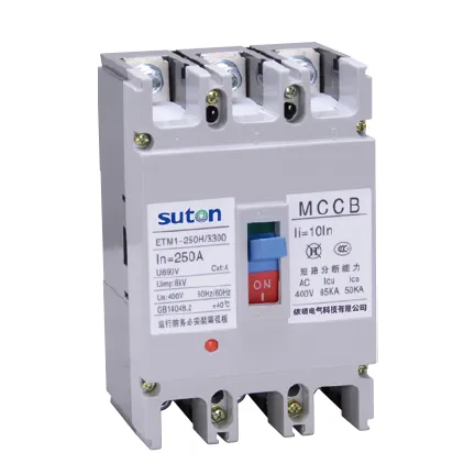
The ETM1 molded case circuit breaker route is relevant when a project is considering that public breaker family and can submit its host configuration and required accessories for review. It is one of the family-level paths shown in SUTON’s modular DIN rail products ecosystem.
Fit Boundary: the public page does not establish an exact auxiliary-switch part, contact arrangement, terminal rating, simultaneous-accessory combination, certification, or project fit. If those inputs are missing, do not recommend a final accessory. Send the schedule, drawing, control logic, and quantity through Contact SUTON for a documented route review.
FAQ
What does an auxiliary switch do?
It transfers a documented host-device state to a separate indication, monitoring, interlocking, or approved control circuit. It does not add the host breaker’s protective function.
How is an auxiliary switch different from an auxiliary contact?
Both terms can describe a state-signalling accessory, but the final meaning must come from the selected host family, accessory marking, and control drawing. Define the intended state and interface rather than relying on the label alone.
Which host-breaker details are required?
Provide the exact series, frame, poles, operating arrangement, accessory position, model reference, and released documentation revision.
What does NO/NC mean on the control drawing?
It describes the contact logic for the documented normal state and change event. Confirm terminal marking and the exact relationship to the host mechanism from the selected device documentation.
How should an auxiliary switch be checked before commissioning?
Compare the host label, accessory marking, wiring identities, indicated state, test point, and record format with the released schematic and approved project procedure.
What should an auxiliary switch RFQ include?
Send the host device, required state, NO/NC logic, receiving circuit, mounting route, related accessories, documents, quantity, and controlled drawings.
When is ETM1 a relevant product route?
ETM1 is a family-level route when the project requires a molded-case breaker arrangement and can provide the exact host configuration and accessory inputs for model-level review.