


A 50 amp label does not specify a conductor size — it triggers an engineering review where installation method, load duty, and protection coordination decide the answer.
Buyers search for wire size because they need a buildable cable schedule, not because a single gauge table exists for every project. Conductor sizing is a calculation under the applicable installation rules; this guide supplies the inputs that calculation needs and quotes no universal wire-gauge prescription.
Important: This guide organizes 50 A conductor-sizing requests for LV panel feeds in line with wiring-system selection practice in IEC 60364-5-52 and assembly integration context in IEC 61439-1. It cannot approve a conductor cross-section, terminal pairing, or protection result where load data, route details, or fault-study references are missing — hold those inputs for engineering review before procurement.
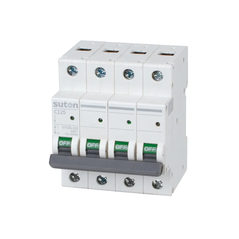
Part 1. Turn a 50 amp wire size request into engineering inputs
A 50 A request can describe a feeder, a large final circuit, or a charging supply — each with different engineering inputs even when the current number matches. Convert the search phrase into a controlled input set before comparing quotations or cable lists.
| Engineering input | Why it matters for the calculation | Send with quote |
|---|---|---|
| Load basis and sustained-duty assumption | fixes the current the conductor must carry | yes |
| Conductor material, insulation, and construction | fixes thermal and mechanical limits | yes |
| Installation method and route | fixes capacity and derating basis | yes |
| Ambient temperature and grouping | fixes correction factors | yes |
| Route length and voltage-drop target | fixes cross-section floor | yes |
| Termination equipment and torque limits | fixes practical cross-section range | yes |
| Protective-device marking and fault-study reference | fixes coordination checks | yes |
| Applicable standards and quantity | fixes approval scope | yes |
Projects that skip the table often receive cable quotations built on nominal current alone. That produces a second cycle once route length, grouping, or terminal limits challenge the delivered size.
Part 2. Record the project inputs that govern the calculation
Identify the actual load profile, expected sustained demand, supply arrangement, conductor material and insulation system, installation method, route, ambient environment, grouping, and any derating conditions. Record the calculated voltage drop and fault-protection conditions for the location.
A feeder, a large final circuit, and a charging supply can each carry a 50 amp label while having different engineering inputs. The cable schedule should name the duty, not only the current.
Part 3. Coordinate conductor, breaker, and fault protection
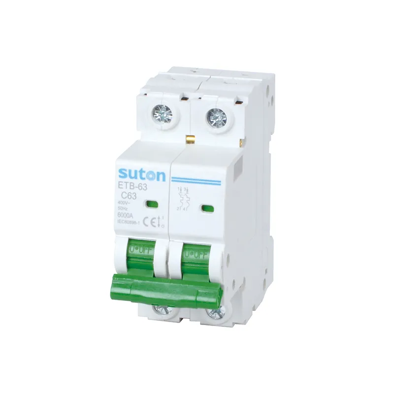
The selected conductor, terminals, protective device, and fault study must be reviewed together. Confirm the protective-device characteristics, available fault duty, disconnection requirements, and the termination temperature or conductor range stated for the exact equipment.
Avoid approving a conductor from nominal current alone, because the limiting condition can be thermal environment, route length, termination, or protection coordination. Frame and device-family context for 50 A positions is covered in the 50 amp breaker guide; this article owns the conductor-side input set.
Part 4. Capture installation details that change the result
Cable containment, bundling, route exposure, enclosure entries, bend space, mechanical protection, and terminal access affect the practical installation. Long runs also require a documented voltage-drop review, while grouped circuits require the project calculation to account for their mutual thermal effect.
Capture these details on the drawing and in the cable schedule before procurement. A size that works on paper but cannot be terminated, routed, or inspected is not a buildable answer.
Part 5. Verify the installed feed against the cable schedule
Verify the delivered conductor identification, route, termination compatibility, torque instructions, protective-device marking, earthing arrangement, labeling, and tests required by the authorized project procedure. Compare the installation with the approved cable schedule rather than substituting based on visual similarity.
Retain the calculation reference and inspection record so later load changes can be assessed properly. Commissioning should reconcile markings and torque values with the released schedule, not with an assumed equivalence.
Part 6. Route a documented 50 A conductor inquiry
Send with the inquiry:
- approved single-line diagram and cable schedule with the 50 A feed highlighted
- load basis, sustained-duty assumption, and route length
- conductor construction, installation method, ambient, and grouping data
- voltage-drop target and termination equipment references
- protective-device marking and fault-study citation
- applicable standards, labeling expectations, and quantity
Require suppliers to confirm conductor range, terminal compatibility, and any exceptions against the controlled documents. Hold the engineering decision when calculation inputs or fault-duty evidence is incomplete.
Fit Boundary: this guide organizes a 50 amp conductor-sizing request for LV panel feeds. It does not replace the project’s calculation, applicable local requirements, manufacturer instructions, or design authority approval. Escalate missing load, route, or protection data before the cable package is priced.
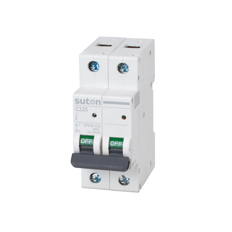
For a documented panel protection route, review SUTON’s ETC65-125 series and molded case circuit breakers. These public pages do not prescribe a conductor size or prove suitability for a particular feed. Send the cable schedule, fault-study reference, terminal data, and approved single-line diagram through Contact SUTON for a model-level discussion.
Cable schedules that stay usable after energization
Treat the calculation reference, route sketch, and termination record as one handover package. Facilities that inherit the package can assess load changes with traceability; facilities that inherit only a cable label tend to uprate by anecdote.
When the feed duty changes — added chargers, expanded sub-board load, or a longer reroute — update the schedule before approving a larger conductor or breaker. The 50 A number may stay the same while the engineering inputs do not.
After any abnormal heating report or protection operation, capture load state, ambient conditions, and recent routing changes before altering the cable size or protection marking.
FAQ
What wire size is needed for 50 amps?
It must be determined from the project engineering calculation, including installation method, load duty, ambient, grouping, route length, terminals, voltage drop, and protection.
Can a 50 amp breaker determine conductor size?
No. The breaker rating is one coordination input, not a universal conductor-size rule.
Why does installation method matter?
Containment, grouping, route exposure, and ambient conditions affect the conductor’s permitted operating conditions.
Should voltage drop be checked on a 50 amp feed?
Yes. Record the route length and load basis in the project calculation, especially for longer feeder runs.
What must match at the terminals?
Verify conductor construction, cross-section, termination range, temperature conditions, and torque instructions for the exact equipment.
What belongs in a 50 amp wire size RFQ?
Include load, route, installation, environment, grouping, voltage drop, terminal, protection, fault-study, standards, and quantity inputs.