SPD earthing system selection requires the confirmed supply arrangement at the actual panel, the SPD's internal protection paths and the manufacturer's approved diagram. TT, TN-S and TN-C-S installations cannot be treated as interchangeable simply because they share a nominal voltage. Neutral-to-earth behavior, the location of an RCD, the separation of neutral and protective earth and the response to an SPD failure all affect the assessment. This guide gives panel buyers a structured way to collect those inputs and select a documented configuration without copying a generic wiring diagram into an unsuitable installation.
Identify the system at the point of installation
The earthing arrangement is a property of the electrical installation, not something to infer from the SPD packaging. In a TT system, exposed conductive parts are connected to the installation's earth arrangement, distinct from the supply neutral's earthing. In TN-S, the neutral and protective conductor remain separate. In TN-C-S, a combined protective and neutral conductor exists in part of the system and divides at a defined point.
These descriptions establish the concepts, but the actual installation must be verified. A downstream panel in a TN-C-S building may have separate neutral and PE conductors. Its connection diagram must correspond to that location rather than to the upstream combined-conductor section. Record where the separation occurs on the single-line diagram.
If an existing panel contains unexplained neutral-to-earth links, do not resolve the uncertainty by copying them. Ask the responsible designer to determine their purpose and whether they are correct. An SPD selection review is not authorization to alter bonding or neutral connections.
Make the internal circuit visible in the documentation
A useful SPD specification identifies the paths between line, neutral and protective earth. Some arrangements limit voltage from the lines to neutral and use a separate neutral-to-earth switching element. Others use paths toward protective earth. The device name and module count may not fully describe that circuit.
Ask for both the internal schematic and the installation diagram. The first explains the protective elements; the second shows the intended connection under the supported system conditions. A four-terminal picture without internal information cannot establish suitability for TT or a particular TN arrangement.
The 3P+N versus 4P comparison explains why common commercial descriptions need this additional verification. Keep the exact order code with the drawing, especially where several variants share one family name or exterior photograph.
TT review: neutral, PE and the RCD relationship
In a TT installation, the design needs to address how the SPD connects relative to residual-current protection and what happens if a protective element fails. Normal leakage and temporary abnormal voltage conditions can also matter. Do not choose a device solely because a quotation calls it suitable for all systems.
A manufacturer-supported arrangement may use a distinct neutral-to-earth switching element. Its behavior is part of the complete product assessment. Verify the declared circuit, the approved position relative to the RCD and the protective requirements for the branch. Do not assume a generic four-module product provides the same function.
The BEAMA surge protection guide discusses SPD connections and residual-current devices in its UK installation context. The project designer must apply the relevant local rules and exact instructions. This review should identify the conditions needing evidence; it should not invent a universal TT wiring sequence for every device.
TN-S review: maintain the separation
For TN-S, confirm that the proposed SPD arrangement is supported for the available line, neutral and PE conductors. Trace the intended paths in the drawing and identify the protective-earth connection point. Separate conductors do not mean that any protective topology is automatically acceptable.
The SPD branch must not become a reason to add a permanent neutral-to-earth bond where the installation does not permit one. A protective element's transient behavior is different from a fixed metallic link. That distinction should be clear to the people reviewing the drawing and installing the panel.
Check continuous voltage and temporary-overvoltage suitability for each relevant path. A line-to-neutral value copied from one product may not establish suitability for a line-to-earth path in another circuit. Compare the complete assembly ratings and documentation rather than selecting individual cartridges in isolation.
TN-C-S review: locate the PEN separation
For TN-C-S, the important initial question is where the SPD is being installed relative to the separation of the combined conductor. A diagram intended for separate N and PE downstream should not be applied casually to an upstream section with a PEN conductor.
Document the supply arrangement and the installation connection point, then request the corresponding manufacturer diagram. Identify any requirements concerning conductor routing, bonding and the local panel arrangement. If the site has altered supplies, backup generation or transfer equipment, verify the system under each operating condition rather than assuming the utility arrangement remains unchanged.
An SPD does not correct a defective PEN conductor or replace the installation's protective measures. Surge limitation and protection against supply-frequency faults are separate questions. A suitable device must fit within a correctly designed earthing and protection system.
Use a system-specific decision table
| System | Evidence needed | Question to resolve |
|---|---|---|
| TT | Local earthing arrangement, RCD position and approved SPD circuit | How are N-PE behavior and SPD failure handled? |
| TN-S | Confirmed separate N and PE and supported protection paths | Does the circuit preserve the intended separation? |
| TN-C-S | PEN separation point and downstream conductor arrangement | Which approved diagram applies at this panel? |
| Multiple sources | System arrangement in every relevant operating mode | Does transfer or generation change the assumptions? |
| All systems | Voltage, surge duty, fault current and backup protection | Is the complete assembly supported? |
| Existing panel | Current drawing and assembly designer review | Is the proposed modification documented? |
This table is deliberately qualitative. A numeric setting or connection prescription would require the exact product and installation evidence. Use it to organize questions for the designer and supplier, not as a substitute for their approved drawing.
The IET's surge protection article explains that devices at different locations need coordination. System selection is one part of that coordination review. Voltage protection, surge duty and installed wiring still need assessment after the earthing topology is resolved.
Match ratings after the circuit is confirmed
Confirm the relevant continuous operating voltage for the actual protection paths. Then compare voltage protection level and the required surge test duty. In, Imax and Iimp describe different declared characteristics and must be compared under the appropriate test conditions. Do not choose a larger kA label as a substitute for a compatible circuit.
Review the protected equipment's requirements and the installed arrangement. The manufacturer's declared protection level does not include every effect of the panel connections. Long or indirect routes can add voltage during a fast surge. The article on SPD lead length covers the connection review.
For facilities with multiple boards, confirm that every stage uses an arrangement supported for its location. A device at a downstream board should not be selected independently of the upstream protection, conductor arrangement and equipment being protected.
Include short-circuit and assembly requirements
The branch requires an assessment of available fault current and any external short-circuit protection specified by the manufacturer. A suitable earthing diagram does not establish that an arbitrary fuse or breaker is acceptable. Record the permitted protective device and the conditions for the declared short-circuit arrangement.
Check conductor capacity, terminal requirements, environmental conditions and compatibility with the assembly. If an existing board is being modified, the assembly designer should assess the proposed components and connection changes. Space in an enclosure is not proof that the modification is supported.
The guide to SPD backup fuse and breaker sizing explains how to keep maximum protective-device limits, coordination evidence and actual design selections distinct. That distinction avoids a frequent procurement error: copying a maximum value into a schedule as if it were an unconditional recommendation.
Review an uncertain site before ordering
Suppose an industrial building has a main switchboard and a remote control panel. The purchasing request says TN-C-S but includes no drawing showing the downstream neutral and protective conductor. Start by obtaining the current single-line diagram and confirming the arrangement at the remote panel.
Next, identify the existing upstream SPD and protective devices. Ask the supplier for the exact candidate's internal circuit and supported diagram. Check the neutral element and ratings against the confirmed system. If the site evidence is incomplete, record the unanswered question rather than approving a product based on the main-board label alone.
Once the design is resolved, keep the approved diagram with the bill of materials and installation instructions. This prevents a later substitution or maintenance replacement from silently changing the protection paths.
Commission and maintain the documented arrangement
Competent personnel should carry out installation, isolation and testing using the applicable instructions and safe working procedures. HSE guidance emphasizes identifying the relevant electrical hazards and using suitable equipment. This article does not provide a live connection or testing method.
At handover, retain the device and cartridge codes, drawing revision, branch protective-device details and monitoring information. Confirm the visible installation corresponds to the approved arrangement. Do not conduct insulation or other tests through an SPD without following its instructions and the applicable test method.
Subsequent changes to the supply, RCD arrangement, neutral treatment, board layout or upstream protection should prompt a review. A record that was valid for the original installation may not describe a modified one, even if the SPD's status indicator remains unchanged.
Request the exact SUTON option
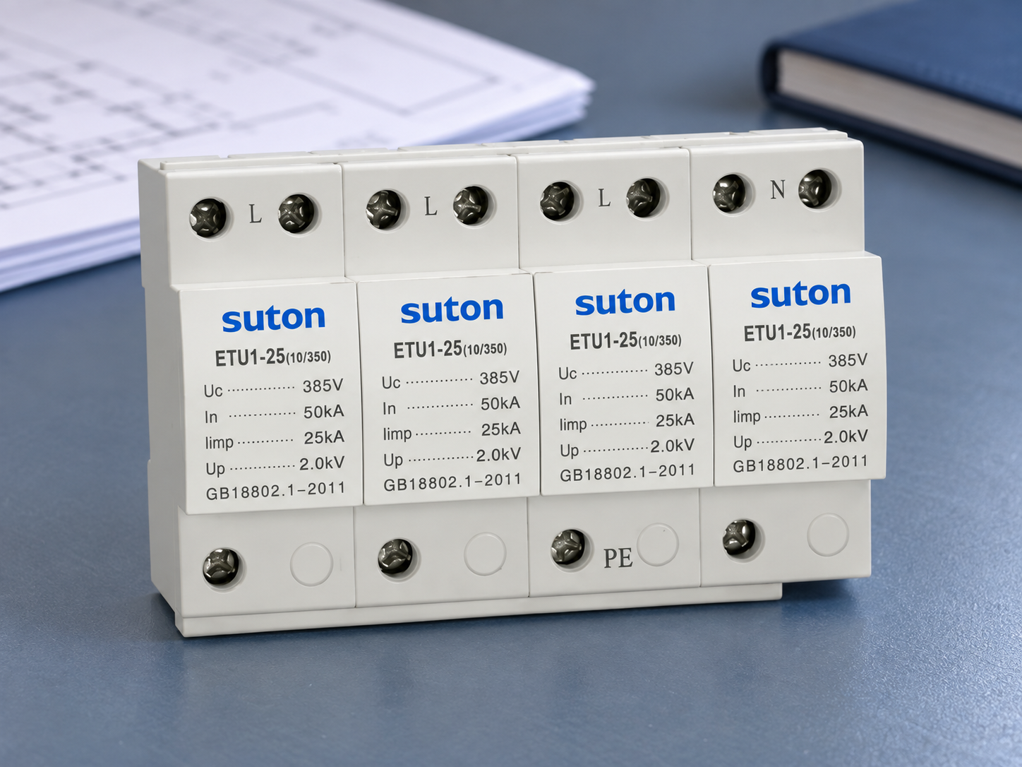
The SUTON ETU1 family page provides a product starting point. Send the confirmed system, supply voltage, panel location, RCD relationship, required SPD class, fault-current evidence and upstream device details. Request the internal circuit and supported diagram for the exact offered model.
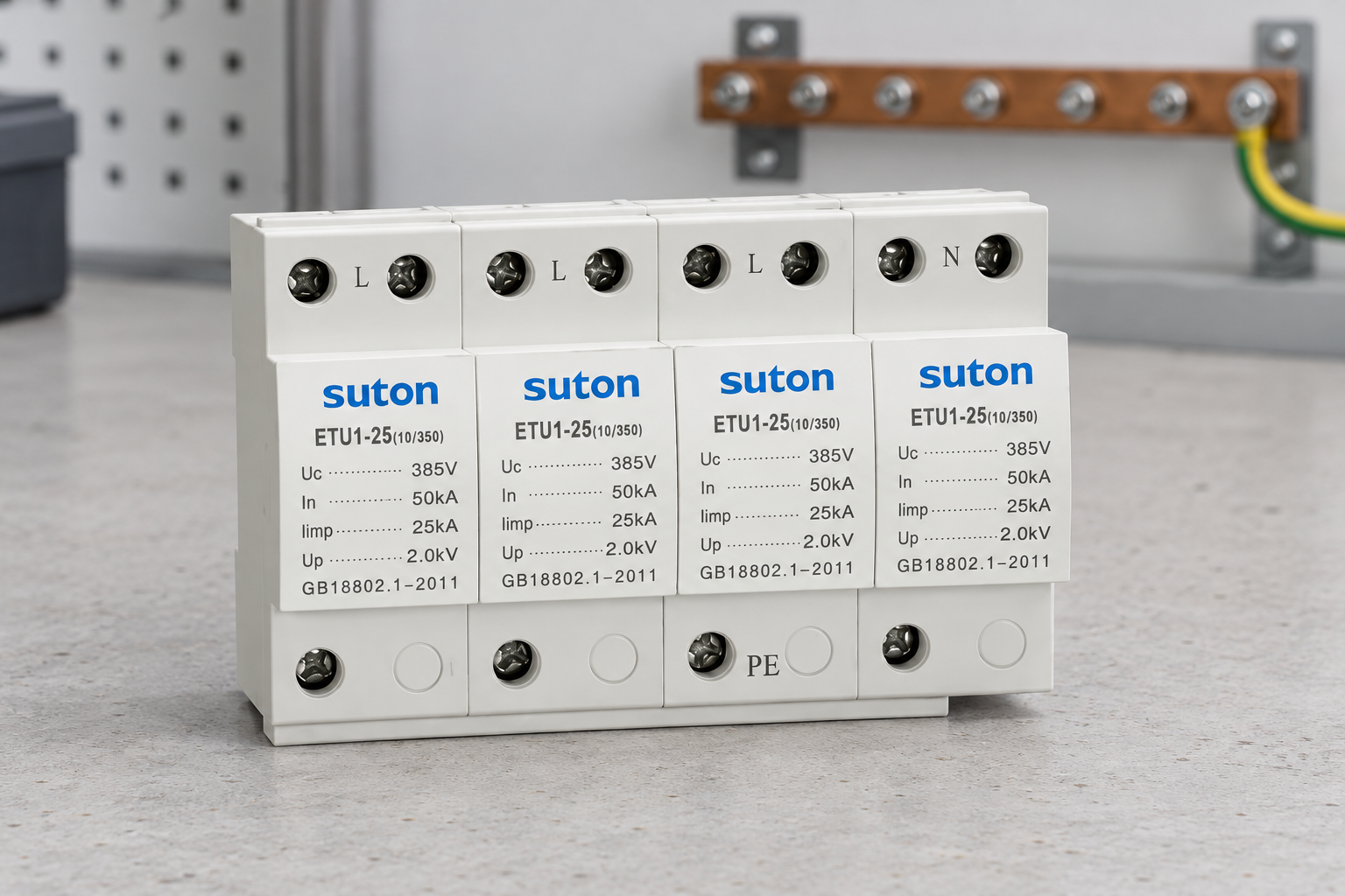
Family illustrations in this article show the photographed product exterior. They do not establish compatibility with every TT, TN-S or TN-C-S installation. Use Type 2 SPD selection as the broader purchasing guide, then resolve the system-specific evidence before ordering.
Frequently asked questions
Can one SPD be assumed suitable for all three earthing systems?
No. Check the exact model's supported arrangements, protective paths and installation conditions. A general family description is insufficient.
Does an SPD create a permanent neutral-to-earth bond?
Its protective elements have specified behavior during normal operation and disturbances. That must not be confused with permission to add a fixed neutral-to-earth link.
Is the main-board earthing label enough for a remote panel?
No. Confirm the conductor arrangement and connection point at the actual panel, including any PEN separation, source changes and residual-current protection.
References and scope
Technical background: BEAMA surge protection guide, IET surge protection explanation, HSE electrical safety guidance. Apply the standards adopted by the project and the exact product instructions. Product illustrations show the photographed SUTON family and do not establish unlisted ratings or installation approvals.
Educational video
Surge Protection – Fundamentals, by IAEI – The Electrical Enforcement Authority, provides general educational background on transient protection. It does not establish model-specific ratings or replace the project design. Its discussion of an installation framework must be checked against the rules adopted by the project.