


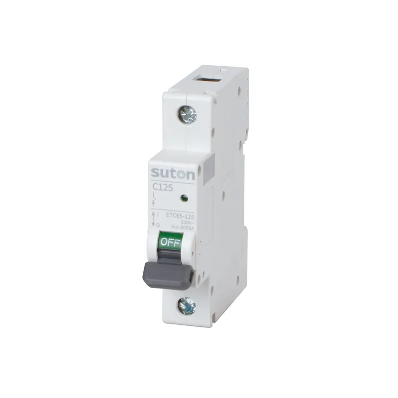
A 100 amp MCB can be a valid high-current modular breaker, but only when the device class, poles, voltage, trip curve, breaking capacity, conductor protection and installation conditions all match the project. SUTON’s ETC65-125 and DZ47 public pages both list 100 A options.
Clarify three similar phrases
| Phrase | What it means | What it does not prove |
|---|---|---|
| 100 A MCB | a modular miniature-circuit-breaker request at 100 A | that every 100 A breaker is an MCB |
| 100 A breaker | a current rating without a complete device-class description | MCB versus MCCB, pole count or curve |
| 100%-rated breaker | a device/application loading concept under stated conditions | a 100 A handle rating |
The live 100 amp breaker guide serves the generic rating intent. This article stays with the modular MCB decision and uses the MCB breaker guide for broader device context.
Specify the high-current modular device
| Field | Evidence to record | Risk if omitted |
|---|---|---|
| Device class | MCB family and applicable standard | an MCCB or other breaker may be quoted instead |
| Rated current | 100 A option in the selected family | frame maximum may be confused with selected current |
| Poles | 1P, 2P, 3P or 4P requirement | topology and isolation may be wrong |
| Voltage | actual AC/DC circuit and device rating | current alone cannot prove suitability |
| Trip curve | load inrush and disconnection requirement | nuisance trips or inadequate fault response |
| Breaking capacity | prospective short-circuit current and device Icu/Ics/Icn | the device may not clear the calculated fault safely |
| Conductor | project ampacity calculation | an oversized setting may leave cable underprotected |
| Environment | ambient, altitude and adjacent devices | published current may require derating |
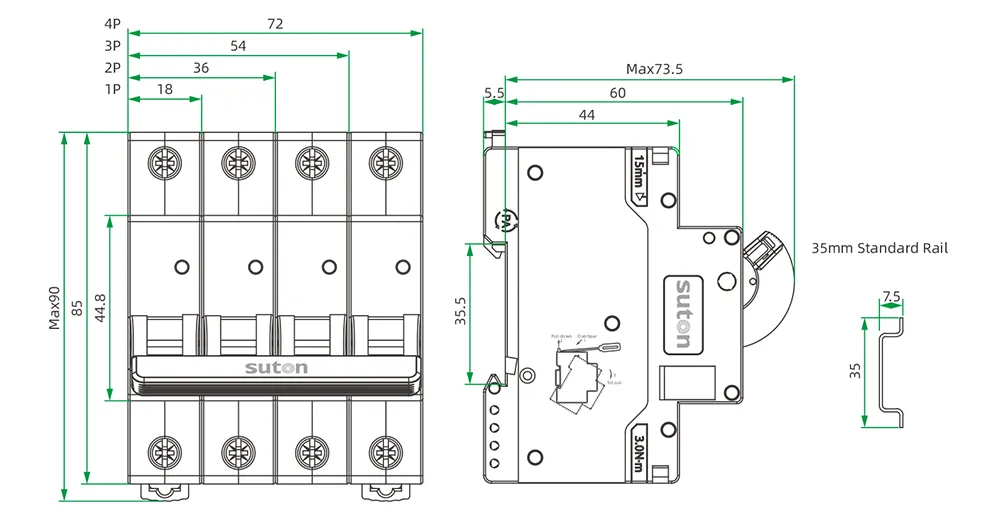
| Interface | DIN rail, terminal capacity, torque and busbar | electrical fit may fail at installation |
High-current modular selection needs derating evidence
The ETC65-125 page publishes an operating ambient range of -30 °C to +70 °C and includes temperature, altitude and side-by-side installation factors. That does not mean 100 A is available without correction throughout every condition. Apply the table for the actual configuration and confirm the panel thermal design.
The same discipline applies to breaking capacity. ETC65-125 publishes 6 kA Icu and 6 kA Ics on its page; compare those exact model values with the calculated prospective short-circuit current at the installation point. Do not transfer the number to another family.
Prepare a complete BOM or RFQ record
Provide:
- circuit role and design current;
- conductor data and installation method;
- system voltage, AC/DC duty and frequency;
- required poles and simultaneous operation;
- trip curve and load-inrush basis;
- prospective short-circuit current;
- ambient, altitude and grouping conditions;
- mounting, terminals, torque and busbar interface;
- auxiliary-contact or other accessory needs;
- applicable standard and required evidence.
Evaluate verified SUTON 100 A modular ranges
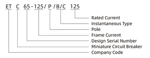
The ETC65-125 Series public page lists 80 A, 100 A and 125 A, with 1P–4P, B/C trip characteristics, DIN35 mounting and 6 kA Icu/Ics. It also publishes environmental and installation correction data.
The DZ47 Series MCB page also includes a DZ47-125 range with 100 A and 1P–4P options. Compare the two families through the modular DIN-rail category, then confirm exact voltage, poles, curve, fault rating, thermal conditions, terminals and accessories before ordering.