


An MCB changeover request is a source-transfer design question — not a catalogue keyword. Panel builders use the phrase when a drawing, generator note, or replacement job asks for manual or automatic source selection without naming the switching duty, isolation requirement, or interlock method.
Start with the approved single-line diagram and operating sequence. Resolve whether the project needs branch overcurrent protection, controlled source transfer, or verified isolation — and keep those duties visible before any quotation is compared.
Important: This guide structures MCB changeover and source-transfer selection for low-voltage panels in line with MCB product scope in IEC 60898-1, switch-disconnector duty in IEC 60947-3, and assembly integration practice in IEC 61439-1. It cannot approve a device marking, interlock arrangement, or fault-duty result where source relationship, earthing arrangement, fault study, or transfer sequence is missing — hold those inputs for engineering review before procurement.
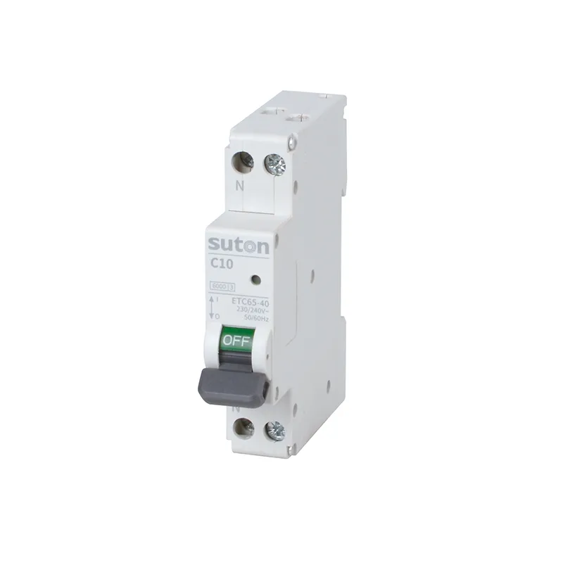
Part 1. Turn an MCB changeover request into documented panel inputs
Ask “which MCB changeover for this panel?” and you are really asking for a controlled source-transfer input set. The phrase appears in different markets for a panel outcome rather than one universal device construction. The approved drawing and applicable installation rules must show whether the request concerns manual source selection, automatic transfer, maintenance isolation, or a combination of those functions.
| Selection factor | Why it matters for the panel | Send with quote |
|---|---|---|
| Normal and alternate source identity and type | fixes what must be switched and protected | yes |
| Nominal voltage, phase, and neutral arrangement | fixes poles and earthing context | yes |
| Required switching sequence and operating positions | fixes transfer logic and labels | yes |
| Isolation requirement and maintenance access | fixes whether a switch-disconnector boundary is needed | yes |
| Interlocking method and parallel-source prohibition | fixes how unintended paralleling is prevented | yes |
| Maximum prospective fault current at each source position | fixes interrupting and making duty | yes |
| Load priority and shedding logic | fixes transfer timing and permitted load | when applicable |
| Enclosure class, cable entries, and assembly interface | fixes physical fit and wiring access | yes |
| Applicable standards and quantity | fixes approval scope and procurement batch | yes |
Projects that skip the table often receive quotations built on a familiar search term alone. That produces a second procurement cycle once switching duty, interlock evidence, or fault duty is challenged on site. Device-family fundamentals stay in the MCB breaker guide; this article owns source-transfer request resolution and RFQ inputs.
Part 2. Separate overcurrent, transfer, and isolation duties
The existing circuit breaker switch guide remains the live article for broader switching-function terminology. This MCB changeover guide does not relabel that page. Instead, it asks the panel builder to resolve the buyer’s requested outcome and keep each defined function visible in the device schedule.
| Protective or switching function | Primary role in a changeover panel | Planning consequence |
|---|---|---|
| MCB / MCCB | Overcurrent and short-circuit protection at a circuit or incomer position | Does not by itself prove source-transfer or isolating duty |
| Switch-disconnector | Defined switching and visible isolation where specified | May be the correct boundary for manual source selection |
| Dedicated changeover / ATS device | Controlled selection between approved sources | Needs documented sequence and interlock evidence |
| Isolator arrangement | Maintenance isolation where the scheme requires it | Must not be assumed from a similar handle profile |
An MCB is selected for overload and short-circuit protection at its installed circuit position. That does not automatically establish the switching category, visible isolation arrangement, or source-transfer interlocking required by a changeover application. Confirm the manufacturer’s instructions, the assembly design, and the applicable project requirements rather than treating a similar handle shape as proof of equivalent duty.
Part 3. Review interlocking and source arrangement
Record each source, nominal voltage, earthing arrangement, available fault current, phase and neutral arrangement, and normal or emergency operating sequence. Capture the load priority and whether any load must be shed before transfer. The panel drawing should show the incomer, outgoing circuits, neutral and protective-conductor arrangements, and the physical space available for interlocking.
Interlocking exists to prevent an unintended source connection that the approved scheme does not permit. It can involve mechanical, electrical, key, or control logic arrangements, but the selected method must be verified against the actual operating sequence — not inferred from pole count alone. Where a generator, UPS, photovoltaic source, or parallel utility supply is involved, the transfer logic must be reviewed as a system rather than inferred from a two-pole or four-pole device label.
Reserve module positions, terminal orientation, bending space, and interlock access from the schematic before the enclosure layout is frozen. A device that clears a nominal-current check but lacks wiring access, lockout provision, or label space often fails the commissioning review.
Part 4. Confirm fault duty and coordination
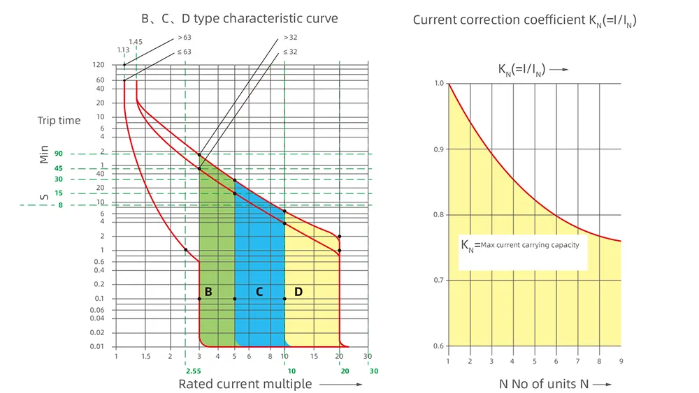
Coordinate the upstream protective devices and branch MCBs using the project fault study; source transfer does not remove the need to confirm interrupting duty at each location. The breaking characteristic and making/breaking capacity must be reviewed against the prospective fault current at the installed position under each source condition the design permits.
Two devices with similar nominal ratings can therefore serve different changeover roles. Keep the changeover function separate in the bill of materials so a later substitution cannot silently turn a transfer device into a general-purpose breaker. File selectivity and backup evidence beside the fault study in the panel dossier; commissioning staff and later service teams will review both documents together.
Where multiple sources can feed overlapping zones, confirm selectivity and backup arrangements from the approved study and manufacturer pairing data. A branch MCB does not become a source-selector merely because it sits on the alternate-source feeder.
Part 5. Verify installation, testing, and commissioning
Before energization, reconcile device markings, terminal arrangement, torque instructions, conductor size, neutral treatment, and enclosure clearances with the approved drawing. Test the permitted source positions under controlled conditions and verify that the prohibited position cannot occur. Document labeling for normal source, alternate source, off or isolation position where provided, and any lockout procedure.
Follow the approved wiring diagram, manufacturer instructions, and authorized test procedure. Record the commissioned device positions and outcomes in the panel dossier. A trip, abnormal voltage, or unexpected transfer should be investigated from the recorded source condition and timing; changing a breaker rating or bypassing an interlock is not a corrective method.
Before handover, reconcile the installed assembly with the approved design. Include the single-line diagram, device schedule, wiring drawing, manufacturer instructions, torque record, inspection outcomes, and operating procedure in the project file.
Part 6. Route an evidence-based SUTON inquiry
Send with the inquiry:
| RFQ input | Why it matters |
|---|---|
| Approved single-line diagram and operating sequence | fixes the source-transfer scheme |
| Normal and alternate source data, voltage, and poles | fixes application conditions |
| Required switching positions and isolation requirement | fixes device family and marking |
| Interlocking method and parallel-source prohibition | fixes how the scheme is enforced |
| Maximum prospective fault current at each position | fixes interrupting and making duty |
| Enclosure class, cable entries, and assembly interface | fixes physical fit and wiring access |
| Applicable standards, labeling expectations, and quantity | fixes approval and procurement batch |
Require suppliers to declare the exact offered marking, switching function, interlock arrangement, installation instructions, and exceptions against the controlled documents. Hold the engineering decision when the source relationship, fault duty, earthing arrangement, or transfer sequence is incomplete — a quotation against an undefined scheme cannot preserve the design intent.
Fit Boundary: this guide is suitable when the source-transfer intent and panel inputs can be documented. It is not sufficient to approve a changeover where the source relationship, fault duty, earthing arrangement, or transfer sequence is unknown. Escalate those gaps to the design authority before the package is priced.
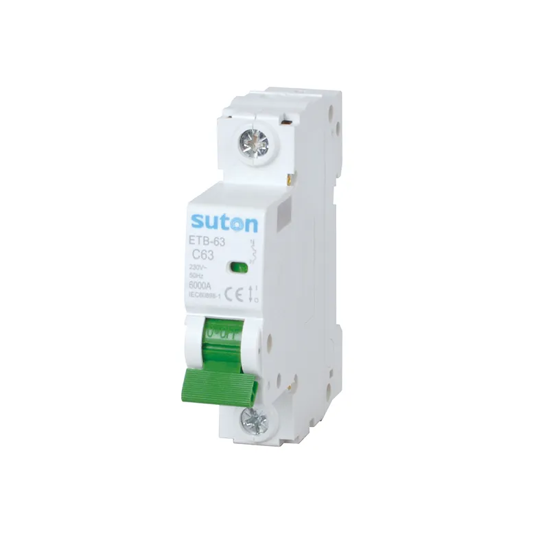
SUTON’s modular DIN rail products provide a public route for modular protection categories. Where the approved design calls for an isolation function at the changeover boundary, review the public DZ47-125G miniature switch-disconnector route as a catalogue starting point and confirm its exact instructions and ratings. This is deliberately not a recommendation to use an MCB as a changeover device.
Send the single-line diagram, operating sequence, fault-study data, device markings, and quantity through Contact SUTON for model-level confirmation. Compare every supplier response against the Part 6 RFQ table and keep the approved device schedule with the source-transfer dossier.
Source-transfer records that survive panel changes
Treat the source-transfer worksheet, device schedule, interlock evidence, test records, and revision history as one handover package. Facilities that inherit the dossier can maintain and expand the arrangement with traceability; facilities that inherit only a search phrase tend to rebuild the review from scratch at the first transfer event.
When sources are added or rearranged — for example a generator retrofit, UPS upgrade, or maintenance-bypass modification — revise the worksheet and schedule before re-energizing. An added source, changed neutral treatment, or swapped transfer device alters fault duty and commissioning scope even when nominal ratings appear unchanged.
After any unexplained trip or transfer, log the source identity, connected loads, and switching context before reset. Repeated log entries often reveal whether a nuisance trip came from wiring, load change, or an operating sequence the original design did not anticipate.
FAQ
What does MCB changeover mean in a panel?
It is a buyer term that must be resolved into documented overcurrent, source-transfer, and isolation duties before a device is selected.
Can an MCB act as a changeover switch?
Do not assume so. Verify the required transfer and isolation duties against the approved design and the manufacturer’s instructions.
Where is the switch-disconnector boundary?
It is where the project requires a specified switching and isolating function rather than only branch overcurrent protection.
What interlocking is required between sources?
Use the method shown by the approved source-transfer scheme to prevent source combinations that the design does not permit.
How is a changeover panel commissioned?
Use authorized procedures to verify labeling, terminals, permitted positions, interlock behavior, and the approved operating sequence before service.
What belongs in an MCB changeover RFQ?
Include sources, voltage, poles, fault duty, operating sequence, isolation requirement, interlocking, enclosure conditions, standards, and quantity.