An SPD module should be replaced when the exact manufacturer's indication or inspection criteria require it, when the module is damaged or unsuitable, or when a documented test establishes a fault. There is no universal calendar interval or reliable number of surges that applies to every surge protective device. A device that still allows the load to operate may already have lost its intended protective function. The replacement decision must follow the model instructions and the installation's condition.
For industrial maintenance teams, the practical task is to identify the affected device, confirm the meaning of the indication, make the equipment safe and fit a compatible replacement. This guide focuses on installed panel SPDs rather than consumer power strips or bicycle products that can share the abbreviation SPD.
Start with the manufacturer's replacement trigger
Find the manual for the complete base and module combination. Identify what the local indicator reports and what a remote alarm represents. A changed color, mechanical flag or open contact is meaningful only under that product's defined conditions. Do not assume that red and green always have the same interpretation across different device families.
If the instructions state that a particular indication requires replacement, treat that as a maintenance trigger. A reset of the monitoring dashboard does not restore the protective element. Equally, do not discard a healthy device simply because another brand uses a different indicator appearance. Record the observed state and compare it with the exact instructions before selecting an action.
The BEAMA surge protection guide places maintenance within the complete protective arrangement. Apply that system perspective: the module, base, connection, backup protection and bonding route all contribute to the result. A visible indication supports inspection but does not replace checking the installation.
Understand why a module may need replacement
Surge protective devices respond to electrical transients according to their technologies and declared duties. Some protective elements can degrade under repeated or severe electrical stress. A device can also be affected by sustained abnormal supply conditions, overheating, incorrect selection or installation faults. These mechanisms should not be reduced to a single universal “surges remaining” counter.
A module replacement may restore the designed arrangement when the damage is confined to a replaceable element and the base remains serviceable. If the base, terminals or enclosure are damaged, replacing only the module may leave a significant defect. Follow the manufacturer's inspection scope and escalate evidence of heating, cracking, contamination or loose connections.
After an important electrical event, use the site's assessment procedure to decide whether inspection should occur before the routine maintenance date. The event's severity and paths may be uncertain. Record what is known, including equipment alarms and supply history, without claiming that a lightning report alone proves the exact stress experienced by the SPD.
Avoid calendar and surge-count shortcuts
A fixed replacement period can be a useful site policy when it comes from a justified asset-management decision. It is not evidence that every SPD becomes unserviceable on that date. Conversely, a recently installed device may need replacement immediately if its specified failure indication appears or it experiences a condition outside its ratings.
Surge exposure depends on the installation, incoming services, lightning environment and electrical activity. Two identical modules can have very different histories. A claim such as “replace after a thousand surges” is meaningless without the surge waveforms, magnitudes, device construction and supporting test conditions. Use documented product limits and actual inspection evidence.
Keep routine inspection intervals separate from replacement triggers. An interval tells the maintenance team when to examine the equipment. A trigger tells them what condition requires action. Mixing the two can create a report that says “checked” while the fault indicated during that check remains unresolved.
Inspect the complete installed assembly
Qualified personnel should inspect the local indication, identification labels, visible condition and relevant connections using an approved safe method. Examine the base and surrounding equipment for signs of abnormal heating or contamination. Check that the fitted modules match the approved ordering codes and that the installation record still describes the actual arrangement.
A remote alarm should be investigated even if the front indicator appears normal. The alarm may represent a signal-circuit issue, module presence or another condition. Establish what the contact detects and test the monitoring chain using a supported method. The related remote signaling guide distinguishes a device fault from monitoring-cable behavior.
Review backup protection and supply conditions when a module has failed. A disconnected fuse or breaker can change the protective arrangement without stopping all loads. Do not judge SPD serviceability solely by whether the cabinet still supplies equipment. Maintenance acceptance should establish that the documented protective branch is restored.
Use a condition-based decision record
The table below supports consistent maintenance decisions without inventing test limits or service-life estimates. For each item, attach the actual product instruction, inspection evidence and resulting action. It is a record framework rather than permission to conduct live inspection or substitute parts.
| Observation | Decision basis | Action |
|---|---|---|
| Specified fault indication | Exact manufacturer replacement criteria | Replace the supported part after safe assessment |
| Damaged base or terminals | Assembly inspection and manufacturer instructions | Assess the complete assembly rather than only the cartridge |
| Normal indication | Routine inspection scope and event history | Continue documented inspection; do not infer remaining lifetime |
| Repeated module failures | Supply conditions, selection and installation evidence | Investigate the cause before another replacement |
| Unverified spare part | Approved module and base ordering codes | Obtain written compatibility before fitting |
When evidence conflicts, keep the discrepancy visible. For example, record “remote alarm active; local indication normal; signaling circuit assessment required.” Do not convert an uncertain condition into a healthy label simply to close a work order. The follow-up should identify who can resolve the difference and which evidence is still missing.
Choose the compatible replacement module
Match the exact base, protective circuit configuration, operating voltage conditions, classification and manufacturer-approved module reference. Similar dimensions or the same printed maximum discharge current are insufficient. The interface, protective paths, thermal mechanism and indication behavior must remain compatible with the complete assembly.
Different modules can be keyed to prevent substitution, but mechanical fit is not a complete electrical compatibility check. Do not defeat a keying feature or alter a module to make it fit. If the original reference is obsolete, request a written supported replacement or a complete replacement assembly. Record any resulting change to the accepted design.
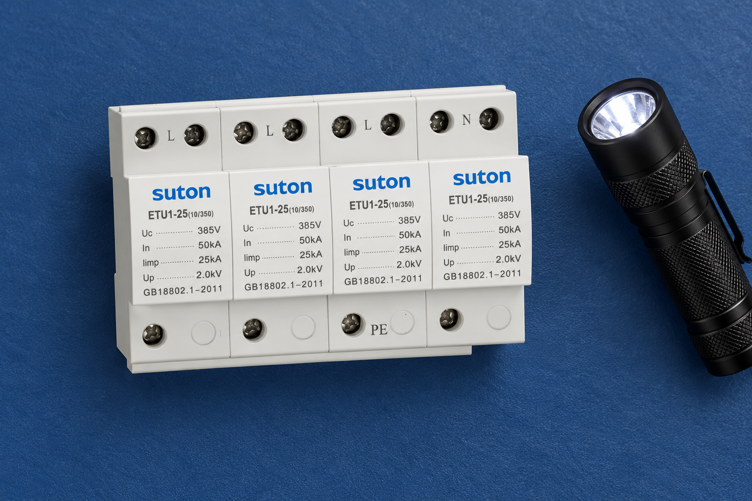
For the SUTON ETU1 family, obtain the exact replaceable-module arrangement and part codes for the supplied version. The product photograph alone cannot establish field replacement availability. It also cannot prove that another model with a similar housing is compatible.
Plan safe removal and installation
Use the manufacturer's instructions and the site's electrical safety procedure to determine isolation and access requirements. Some products are described as having pluggable modules, but that does not automatically authorize removal under every energized condition. Nearby power terminals and other sources can remain hazardous even when a module itself appears easy to handle.
The HSE guidance for work near electricity explains why planning and control of electrical work matter. Identify all relevant sources, arrange the required isolation and verification, and use competent personnel. A maintenance article cannot determine the safe method for an unknown cabinet.
Before removal, record module positions and identification. Inspect the base according to the permitted procedure. Install the approved replacement without damaging its interface, and apply only the manufacturer's specified connection or mechanical requirements. Do not invent a universal torque or cleaning agent; these depend on the actual materials and terminal design.
Verify the result after replacement
Check that the correct module is fully fitted under its instructions, the local indication is in the expected state and the remote signal has returned correctly. Verify the upstream protective branch and other relevant connections through the agreed commissioning checks. Save the replacement code, date, technician and outcome in the asset record.
If a monitoring alarm clears, record what that proves: the monitored state and signal chain have returned to their expected condition. It does not establish laboratory impulse performance. The SPD inspection and testing guide explains the difference between routine field checks and tests of surge protection characteristics.
Review whether the replacement changes any spare-parts or monitoring documentation. Update the label and stock record with a supported equivalent reference where applicable. Keep the original failure evidence rather than overwriting it with the successful final state, so future repeated failures can be analyzed.
Investigate repeated failures before closing the case
Repeated failures require a wider review. Confirm the maximum continuous operating voltage, actual system arrangement, abnormal supply history, surge duty, backup protection and installation conditions. Check for unsupported substitutions or a mistaken assumption about the device's application. Use the SPD ratings guide to organize the relevant parameter review.
Do not assume that fitting a larger current rating solves every cause. A voltage mismatch, unsupported protective path or damaged connection may remain. The correct response comes from the observed condition and exact manufacturer evidence. Where the installation has changed, the original selection may need reassessment rather than a simple like-for-like purchase.
Send SUTON support the complete assembly references, photos of the observed state, installation drawing and failure history. Ask for the supported replacement and any checks required before energization. This gives purchasing and maintenance teams a traceable decision instead of relying on an appearance match.
Frequently asked questions
Should every SPD be replaced after a fixed number of years?
No universal replacement age applies to every device. Follow manufacturer criteria and the installation's maintenance policy. Inspection intervals and replacement triggers should be recorded separately, and any specified fault indication requires the documented response regardless of age.
Can I replace a module with another brand that fits the base?
Physical fit does not establish electrical or indication compatibility. Use the exact approved replacement or obtain written support for an alternative complete arrangement. Do not modify keys or interfaces to force an unsupported module into the base.
Does a cleared alarm prove the replacement has full surge performance?
It establishes only the monitored condition and tested signal-chain behavior. Correct parts, installation checks and documented manufacturer evidence support acceptance. Routine alarm checks do not independently reproduce the laboratory tests used to establish surge protection characteristics.
Additional safety reference
HSE electrical safety guidance explains the need to control electrical risks during inspection and replacement.
Educational video
Surge Protection – Fundamentals, by IAEI – The Electrical Enforcement Authority, explains the general protective arrangement. It does not provide a model-specific contact, replacement or field-testing procedure.