Size a switch disconnector for a motor by checking its operational rating at the actual voltage, its supported motor-switching duty, the motor's current and starting arrangement, and the declared short-circuit coordination. Selecting solely by the largest ampere number on the housing is insufficient. The device must also provide the isolation function, enclosure arrangement and operating mechanism required by the installation.
For an industrial buyer, the useful result is a documented model and accessory combination with a defined service role. This guide explains what to send to a supplier, how to compare its response, and where apparently simple motor-current calculations can conceal unsupported assumptions.
Establish what the switch will do
Start with the operating sequence. Will the switch close onto a stopped motor, interrupt a running motor, or provide maintenance isolation after a contactor has removed current? Record normal operation and foreseeable situations. A written instruction to stop the motor first is useful only when the installation and procedure reliably support it.
Distinguish a local maintenance switch from the device used for routine process control. A rotary switch near the machine can have a clear isolation role while the starter performs normal control. If operators begin using the maintenance switch to start and stop production, its switching duty may change even though the motor itself stays unchanged.
The IET explanation of protective, isolation and switching devices distinguishes these functions. Use that distinction as a review framework, while applying the standards adopted by the project. A front handle and an OFF mark do not by themselves establish every required function.
Collect the motor and supply information
Obtain the actual motor nameplate and circuit drawings. Record supply voltage, frequency, phase arrangement, rated motor current, output power and starting method. Identify multiple motors or auxiliary circuits on the same switch. A catalog motor-power example cannot automatically represent a different voltage or motor construction.
For an existing installation, compare the drawings with the equipment identification before ordering. A replacement motor, changed supply or added drive may make an old selection sheet obsolete. Ask the responsible engineer to resolve inconsistencies rather than choosing the larger of two numbers and assuming that all other conditions become acceptable.
Keep operating current separate from starting and fault conditions. Each describes a different duty. If a supplier offers a motor-power rating, request the voltage and assumptions behind it and the corresponding operational current information. This helps prevent an offer for one supply from being accepted for another.
Use the relevant utilization-category rating
A utilization category gives context to the load-switching duty. Motor switching can require different evidence from carrying the same current continuously. Read the category with the operational voltage and current, not as an isolated label. The same frame can have different ratings for different conditions.
The AC-22A versus AC-23A guide explains the category comparison separately. For this selection, ask the supplier to identify the category that supports the intended operation. Do not assume a thermal-current figure is the supported motor-switching current, or that a category declaration approves every starting method.
The IEC 60947-3 publication scope covers the relevant low-voltage switching and disconnecting product framework. The public scope does not supply a model's ratings. Retain the applicable product documentation and project-standard requirements as the acceptance evidence.
Avoid a universal oversizing multiplier
An arithmetic allowance cannot replace missing switching evidence. Multiplying the motor current by an arbitrary factor might increase the continuous-current margin while leaving utilization category, fault coordination or drive compatibility unresolved. It can also produce a larger enclosure and terminal arrangement without solving the real selection question.
Suppose the project file lists a motor rated at 24 A on its actual supply. That figure is an example input, not a SUTON specification. The buyer still needs the candidate's supported operational rating for the intended duty at that voltage. A headline 32 A, 40 A or 63 A figure alone does not complete the review.
Use a calculation only when its rule, source and conditions are identified by the designer. Document the input units and resulting acceptance criterion. Keep that calculation alongside the model evidence, so a later change in voltage, motor or duty triggers review instead of silently carrying forward an old recommendation.
Review drive-fed motors as a complete arrangement
A variable-speed drive introduces questions about the switching location and operating sequence. Is the disconnector on the drive input or between the drive and motor? What do the exact drive instructions permit? Ask these questions before treating either location as interchangeable.
Opening a drive's output circuit while it is operating can fall outside the permitted procedure for the particular equipment. A stop command and electrical isolation also serve different purposes. Obtain the drive manufacturer's instructions and the machine designer's approved sequence; do not infer permission from a switch's general motor rating.
The review should include residual energy and auxiliary supplies. A motor may stop while a drive's internal circuits remain energized. The maintenance procedure must address the actual equipment, its stated discharge conditions and verification steps. This article supplies selection questions, not a substitute timed isolation procedure.
Compare candidates using separate evidence fields
The following checklist keeps continuous current, switching duty and protection from being collapsed into one purchasing number. Each accepted field should refer to a document revision or approved project record, making differences between offers visible.
| Selection field | Project input | Evidence required |
|---|---|---|
| Supply | Actual voltage and frequency | Operational rating at this supply |
| Motor | Nameplate current and starting method | Supported switching duty for this load |
| Service role | Maintenance isolation or routine control | Permitted operations and endurance conditions |
| Drive | Input/output location and drive identity | Exact drive instructions and accepted sequence |
| Fault duty | Available fault assessment and upstream protection | Supported protective-device coordination |
| Assembly | Enclosure, conductors, mechanism and access | Model instructions and compatible accessory codes |
If an offer leaves a field blank, identify the unresolved question rather than interpreting silence as approval. A supplier's confirmed operational rating is stronger evidence than an unexplained “suitable for motors” statement. Resolve critical fields before comparing price, delivery or accessory appearance.
Confirm short-circuit coordination
A switch disconnector does not automatically clear overloads or short circuits. Establish the available fault conditions at its installation point and the manufacturer's supported protective arrangement. Exact fuse or breaker identity, ratings and any relevant settings can matter to the declaration.
The making and breaking capacity guide separates ordinary switching from short-circuit making, withstand and conditional ratings. Do not import a circuit breaker's interruption terminology into a switch specification without checking the product's actual declared quantities and conditions.
Keep the protective-device selection in the panel design record. If the upstream device later changes, reassess the supported arrangement. A replacement that has a similar current rating or fits the same space can still change the evidence on which the switch selection depended.
Check the enclosure, terminals and mechanism
Verify ambient conditions, enclosure heat, mounting position and any specified installation limits. The motor's running current is only one part of the thermal assessment. Request how the manufacturer's rating applies inside the proposed cabinet, including any stated derating or conductor conditions.
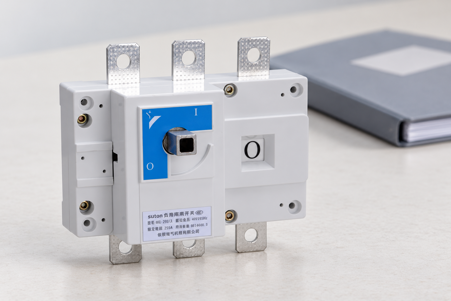
Record conductor size, conductor type, terminal arrangement and the exact installation instructions. Avoid prescribing an unverified tightening torque from a photograph. The assembly team needs the correct model's terminal and torque information, and enough access to follow it without modifying the approved construction.
For a door-coupled mechanism, obtain the compatible shaft, handle, coupling and installation dimensions. Check the required indication and locking function as part of the complete assembly. A loose operating shaft in a product image cannot establish enclosure compatibility or an accepted maintenance lockout arrangement.
Plan safe isolation around all energy sources
Electrical isolation belongs within the machine's maintenance process. The HSE guidance on equipment maintenance addresses stopping equipment and isolating electrical and other energy supplies. Apply that broader view where motion, pressure, gravity or stored energy can remain hazardous.
Identify additional electrical feeds, control transformers and externally powered accessories in the work boundary. A main motor switch may not isolate a separate control supply. Update labels and procedures to match the accepted arrangement, with verification performed by competent personnel under the site's rules.
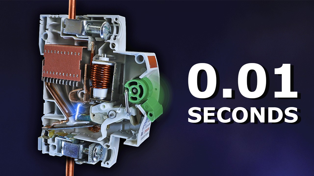
The educational video below explains why a circuit breaker is not a complete answer to electric-shock protection. Its role here is safety background. It does not give permission to work on a motor circuit or replace the equipment-specific isolation procedure.
Prepare an inquiry that can be answered
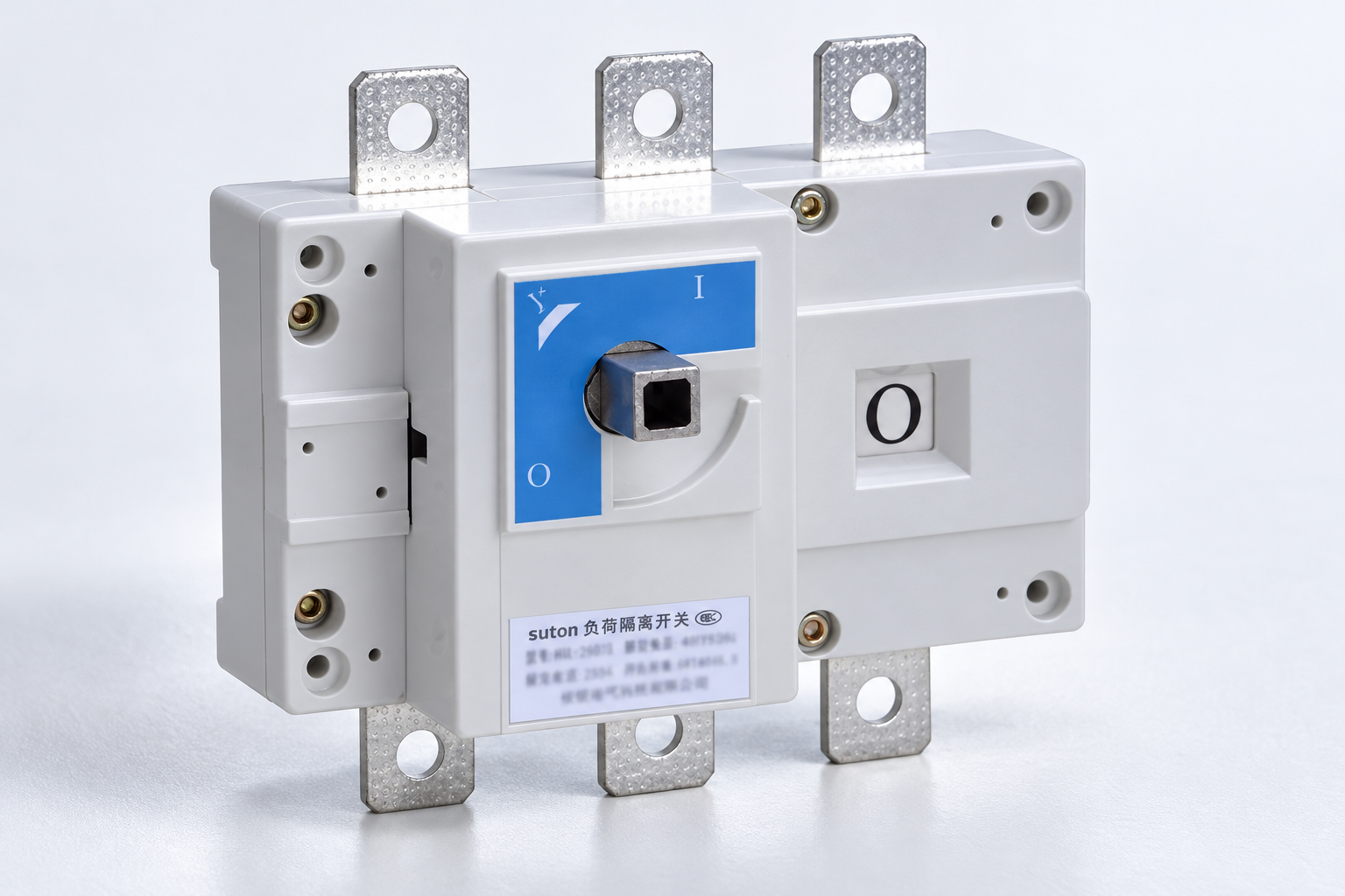
For the SUTON ETGL(HGL) load-break switch-disconnector family, send the motor data, supply details, switching role, operation frequency and drive information where relevant. Include the fault assessment and proposed upstream protection, then request the supported exact model and documentation.
Send enclosure and mechanism requirements at the same time. Splitting the electrical selection from the handle and mounting order can produce an incomplete assembly. Ask for a single response covering the switch, compatible accessories, rating conditions and installation instructions.
The panel-builder switch-disconnector guide provides the broader selection context. Use SUTON support to resolve remaining product questions. Accept a traceable configuration whose service role is clear to purchasing, assembly and maintenance teams.
Frequently asked questions
Can I select by motor running current alone?
No. Running current is an essential input, but the selection also needs the actual voltage, supported switching duty, short-circuit coordination and installation conditions. Obtain the candidate's operational rating for the intended motor application.
Is a switch disconnector a replacement for a motor starter?
Do not assume so. Establish the device's intended role and supported operations. Normal motor control, overload protection and maintenance isolation can involve different devices and requirements within the complete arrangement.
What should I do when the motor uses a drive?
Identify the proposed switching location and obtain the exact drive instructions and approved operating sequence. Review residual energy, auxiliary supplies and the switch's supported duty before selecting an input-side or output-side arrangement.
Educational video
Why Circuit Breakers DON'T Protect People (electric shocks) by The Engineering Mindset. Educational background on why switching or circuit protection is not a complete safe-isolation procedure. It does not establish switch ratings or provide a model-specific work instruction.