Smart circuit breaker BMS integration connects documented electrical measurements and device states to a building management system, usually through a supported device interface and sometimes through a gateway. Successful integration requires more than matching a cable or selecting a protocol name. The project needs a verified point list, units, data quality, update behavior, alarm responsibilities and ownership of any write commands. Here BMS means building management system, not battery management system. This guide helps panel builders and facilities teams define a monitoring connection and its acceptance evidence without assuming that a particular breaker supports BACnet, Modbus, remote switching or billing-grade measurements.
Decide what the building system needs to know
Begin with the operational questions. A facilities team might need feeder availability, present load, energy consumption trends and communication alarms. An energy analyst may need interval consumption with consistent timestamps. A maintenance team may need a trip indication with an event record. Each question implies different data, timing and retention requirements. Listing hundreds of available registers before identifying the users often creates an expensive screen with little practical value.
Write one requirement for each intended use. For example, a feeder trend may need phase currents and a valid-data indicator, while a monthly consumption report needs energy-counter behavior and a documented treatment of missing periods. Do not substitute a calculated value when the required source quantity is unavailable without identifying the calculation and its limitations. The smart circuit breaker metering guide explains why accuracy, resolution and quantity definition need separate review.
Draw the connection from field device to application
A typical proposal might include a breaker, communication accessory, serial connection, gateway, building network and BMS server. Another device might use a supported network interface directly. Neither arrangement should be assumed from the product category. Identify the exact parts and the owner of each boundary. A gateway can translate supported data, but it cannot create a measurement or physical operating function that the original device does not provide.
Record where values are scaled, timestamps are assigned and communication errors are detected. If both a gateway and the BMS convert a raw current value, an apparently believable result may be wrong by a constant factor. Decide which component owns each conversion, and keep the original source definition alongside the mapped point. Review the communication options article when choosing the supported interface and collecting its documentation.
Check protocol compatibility beyond the name
BACnet and Modbus are different protocols, and an RS485 connection alone does not identify either one. A device register map must match the supplied hardware and firmware. A gateway needs a documented mapping between its source points and the objects or points it presents to the building system. Identify the actual supported profile, transport and functions before a compatibility claim enters the purchase order.
The BACnet International glossary provides terminology for building automation communications. Its definitions help teams discuss the network consistently; they do not certify a particular SUTON product or gateway. If the specification requires independently tested interoperability, request evidence for the exact product rather than accepting a protocol logo in a general presentation.
Create a point list that can be tested
The point list should contain a unique name, source address or object, readable description, quantity, unit, scaling, signedness where relevant, access permission and expected quality behavior. Record which points are required and which are optional. A blank source address is an unresolved requirement, even if the screen layout already contains a convincing label. Version the point list so the panel supplier and BMS contractor work from the same approved document.
Separate a measured value from a derived value. Total power, phase power, apparent power and energy have different meanings. An open/closed signal and a trip indication also answer different questions. Do not combine them into one status unless the available evidence supports every displayed state. Where the device cannot distinguish two conditions, show the limitation instead of presenting a false level of certainty.
| Point group | Document before mapping | Verify at acceptance |
|---|---|---|
| Current and voltage | Quantity, phase, units, scale and valid range | Raw definition agrees with displayed value |
| Energy counter | Direction, retention, reset and rollover | Interval calculations preserve continuity |
| Device state | Meaning of open, closed, trip and unknown | Display distinguishes unsupported or stale states |
| Communication | Quality, acquisition time and alarm ownership | Disconnection never appears as healthy live data |
| Control if approved | Write permission, feedback and inhibition | Monitoring access does not grant switching authority |
The table is a commissioning template. It contains no claimed ETM3E data-point availability or performance rating. Populate it only from the approved device map and the project's intended use, then test each required item end to end. Unsupported points should be removed from the committed scope or provided through a separately approved measurement arrangement.
Make missing data visible
A supervisory display should tell the operator when a value is unavailable or stale. Showing the last valid current as though it were live can hide a failed gateway. Replacing missing energy data with zero can distort a consumption report. Define the age and quality information that accompanies values, the conditions that raise communication alarms and the method used to distinguish a restored connection from a genuinely new event.
Some devices timestamp events locally; others provide values that receive a timestamp at the gateway or server. Record which applies. A timestamp assigned after a connection returns may describe collection time rather than event time. If reliable event ordering matters, request the necessary clock behavior and synchronization evidence. Do not promise incident reconstruction accuracy from a system that only polls current status.
Define trends and energy calculations
Choose the trend interval from the intended analysis and the capabilities of the complete system. Faster collection is not automatically better if it overloads a serial network or produces redundant data. Document the practical relationship between acquisition, storage and reporting. Test the selected arrangement with the expected device count, because a single-device demonstration does not establish the response of a populated panel network.
For an accumulated energy counter, interval consumption is the later valid reading minus the earlier valid reading only when the counter definition and continuity permit that comparison. Review resets, rollovers, replacement, reverse energy direction and outages before using this calculation. Label estimated or incomplete periods explicitly. Billing and contractual settlement require their own approved measurement basis; integration into a BMS does not establish that approval.
Give alarms a responsible owner
An alarm needs a meaning, recipient, priority and response. Decide whether the breaker, gateway or BMS detects each condition. Avoid generating several indistinguishable notifications for one communication failure. The operator should be able to tell a feeder trip from a gateway outage and a process problem from a missing measurement. Preserve enough source information to support investigation without forcing an operator to read raw protocol transactions.
Define acknowledgment separately from correction. Clicking acknowledge should not imply that a protective trip has been investigated or cleared. If an alarm remains active, its continuing state should remain visible under the site's agreed workflow. Review alarm presentation with the actual facilities team and document its response responsibilities before the project is handed over.
Keep monitoring and control separately approved
A read-only integration is often sufficient for trending and energy reporting. If control is requested, specify it as a separate function with authorization, inhibition, feedback and failure behavior. An energy dashboard should not acquire power-switching authority simply because its gateway supports writable registers. Disable unnecessary write paths using the approved device and network configuration.
For projects that require remote operation, refer to the remote trip and reclose review. That guide addresses operating permission and confirmation of state. The BMS specification should identify whether any control is included, who owns the operating procedure and how a failed or uncertain command is handled. Avoid assuming that a remote opening request creates a maintenance isolation.
Plan security at every connection boundary
Identify who owns the gateway, network connection, user accounts and support arrangement. Document required services and restrict access to the approved routes. Avoid placing a device directly on an unrestricted network merely to simplify commissioning. A temporary engineering connection needs a removal date or a controlled transition into the permanent operating arrangement.
NIST SP 800-82 Revision 3 addresses operational technology security, including the need to consider physical operational effects. Apply the relevant project controls through the responsible IT and facilities teams. This article's integration checklist is a procurement aid, not a claim that a product or installation complies with that guidance or with a cybersecurity certification scheme.
Review the actual SUTON product and evidence
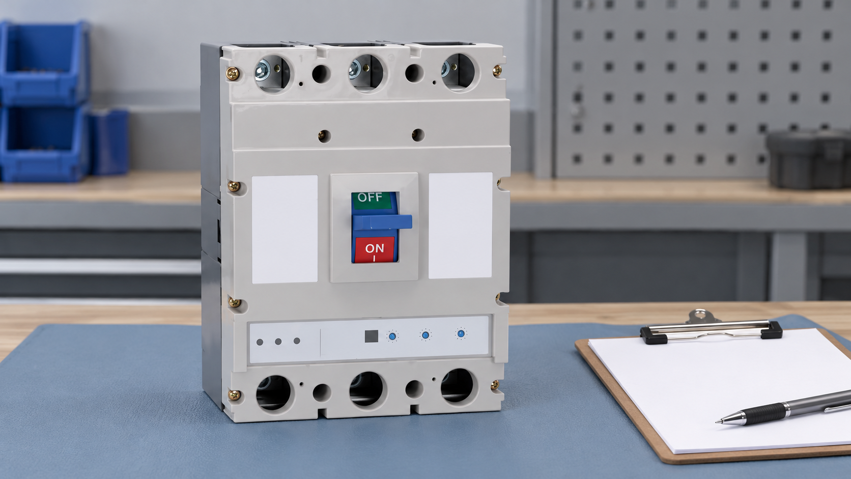
Use the ETM3E intelligent measurement circuit breaker product page to begin the product discussion. Obtain the exact model, communication accessory, firmware version, point map and installation instructions before confirming an integration design. The published family description and exterior image do not independently establish BACnet support, Modbus support, interface isolation, a particular accuracy class or remote closing capability.
Ask for a written compatibility response using the BMS platform and gateway version proposed for the project. Include the required points and their intended purpose. Request sample transactions or a controlled demonstration where appropriate, with sensitive settings removed from shared documents. A supplier should be able to identify which requirements are supported directly, which require an accessory and which remain outside the product's scope.
Run a traceable acceptance exercise
Start with one identified point and trace it from the device documentation through the gateway to the screen and exported trend. Confirm the raw definition, conversion, unit, label and quality. Then repeat for the required quantities and states. Use an appropriate reference method agreed by qualified personnel when checking measured values. A screen matching another screen is not independent evidence of measurement accuracy.
Test disconnection and restoration in an approved controlled environment. Confirm that stale values are marked, communication alarms reach the intended recipient and the trend does not fabricate valid data during an outage. Check that a gateway restart retains its mapping and permissions. Retain results, configuration versions and known limitations in the handover package rather than relying on a verbal statement that the network was working.
Assemble the integration handover
The handover should include the final point list, connection diagram, configuration backups, device identities, firmware versions, account ownership and acceptance records. Record the support contacts for both electrical equipment and the BMS. Define who approves changes when a replacement breaker or gateway arrives with a different map. This prevents a later substitution from silently changing quantities or control permissions.
For broader panel planning, the smart panels guide helps place monitoring within the assembly's overall requirements. A successful integration gives operators dependable information with known limitations. It should make the source and quality of a value understandable, while retaining clear electrical and operational responsibilities.
Frequently asked questions
Can every smart breaker connect directly to a BMS?
No. Confirm the exact interface, protocol, point map and supported platform. Some arrangements need a compatible gateway, and others do not expose the required information. A smart label does not establish interoperability.
Is a gateway enough to make energy data suitable for billing?
No. A gateway translates or transports available information. Billing suitability depends on the approved measurement arrangement, applicable requirements and documented accuracy and counter behavior, not merely on connection to a building system.
Should the BMS be allowed to close the breaker?
Only when the complete operating function and procedure have been explicitly engineered, authorized and accepted. Monitoring permissions should remain separate from control permissions, with appropriate local conditions and feedback.
Educational video
Power Factor Explained – The basics what is power factor pf by The Engineering Mindset. This educational background explains active and apparent power and power factor, quantities that a BMS point list must distinguish. It does not establish SUTON metering accuracy or interface compatibility.