


This MCB box guide turns a search term into a panel-builder verification process: document the circuit position, electrical duty and physical interface before selecting a device or assembly.
Part 1. What is an MCB box?
An MCB box is an assembly planning term for the enclosure, DIN rails, busbars and modular protective devices that distribute power to final circuits. It is not merely an empty metal cabinet: the finished assembly must keep clearances, thermal limits, neutral/earth arrangements and protective-device coordination intact. SUTON’s public product catalogue focuses on protection devices; where an enclosure is not listed, treat the enclosure as an RFQ requirement rather than a promised stocked SKU.
Part 2. Which inputs define an MCB box?
Start with the circuit schedule. For every outgoing circuit record voltage, design current, poles, curve, RCBO or MCB requirement, cable size and load description. Then record the incomer rating, prospective fault current, IP requirement, cable entry, indoor or outdoor location and required spare ways. A way count alone is not enough because RCBOs, SPDs and main devices occupy different module widths and depths.
Part 3. How do you plan modules and spare ways?
Add each device’s documented module width, then reserve space for future circuits and service access. A typical project reserves 20–25 percent free module capacity, but the project specification controls. Group circuits according to the single-line diagram so neutral and earth conductors remain traceable. Do not crowd modules simply to fit an advertised way count; wiring bend radius, heat dissipation and labeling clearance also affect the usable layout.
Part 4. How should busbars and rails be checked?
Busbars distribute line current while DIN rails support devices; they are not interchangeable functions. Verify busbar current and short-circuit withstand against the assembly study, then confirm the comb-busbar tooth pattern, device pole pitch and blanking pieces. An MCB that clips to a rail may still be incompatible with a particular comb-busbar interface. The DIN rail guide provides mounting context, but the approved assembly drawing remains decisive.
Part 5. Which protection accessories belong in the box?
MCBs handle overcurrent. RCBOs add leakage protection for selected circuits, RCCBs can protect groups, and SPDs address surge events when the project calls for them. Specify each device by protection function rather than filling a box with generic modules. The residual current circuit breaker guide helps distinguish leakage protection from overload protection.
Part 6. What is the verification and RFQ boundary?
Before manufacture, compare the circuit schedule, single-line diagram, device list and enclosure drawing. Confirm voltage, fault level, incomer duty, module count, neutral/earth bars, IP rating and labels. Fit Boundary: this guide works when the circuit schedule and panel conditions are documented; hold the RFQ for engineering when the fault level, enclosure environment or source arrangement is unknown. Never treat an empty MCB box description as enough information to select protection.
Part 7. Where do SUTON lines fit?
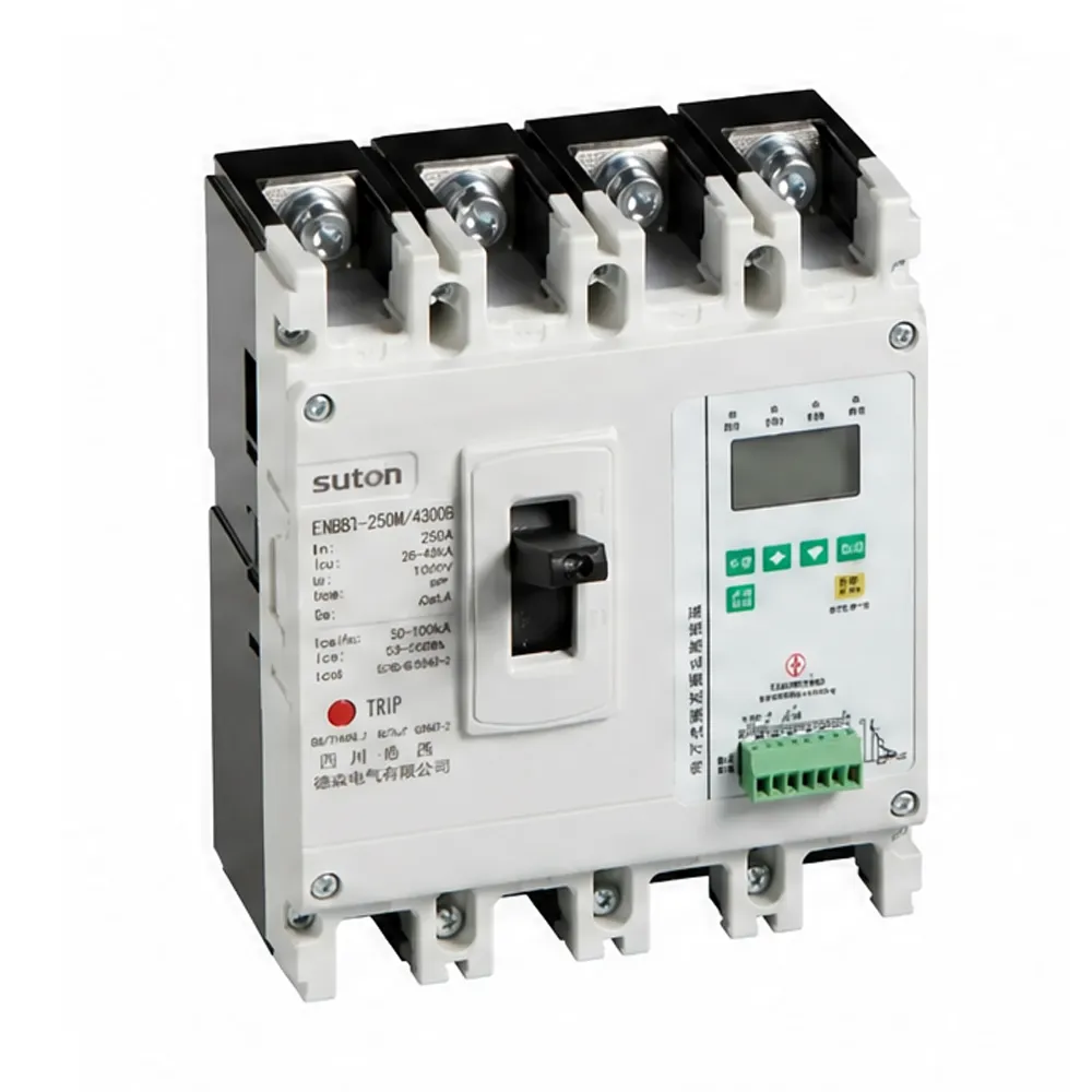
For modular branch protection, start with DZ47 Series MCB and the modular DIN rail products category. For feeder-level selection, review ETM3E intelligent MCCB after the fault study. Send the schedule, module layout, voltage, poles, prospective fault current and quantities through Contact SUTON for confirmation.
Engineering review notes
Use the approved single-line diagram as the control document. It identifies the source, incomer, branch locations and device hierarchy that a catalogue search cannot show. Compare each proposed item against that drawing before the purchase order is released. A mismatch between the schedule and the installed assembly should be corrected in design review, not improvised during commissioning.
Record the prospective fault current at the exact device location, including the operating source arrangement. A final circuit at the end of a long cable can have a different duty from a feeder close to a transformer. If the project changes transformer impedance, generator mode, parallel source configuration or conductor route, review the protection study again. The original label is not evidence that the new duty is unchanged.
Treat panel temperature and wiring space as selection inputs. Closely packed modular devices can operate in a warmer environment than a catalogue reference condition. Allow routing space for conductors, neutral tails, earth conductors and identification labels. Inspect terminal compatibility for the specified conductor size and do not force a conductor or busbar tooth into a terminal intended for a different arrangement.
Commissioning should follow isolation, visual inspection, torque verification and controlled energization. Verify that labels identify the circuit, protective device, poles and isolation points. Test only with authorized methods and qualified personnel. If a device trips on initial energization, capture the load condition and timing before changing its rating or curve; this evidence is more useful than a replacement request without a fault description.
For procurement, distinguish a confirmed requirement from a design assumption. Confirmed data can be priced and supplied; missing data should be marked as a hold item. This approach prevents the common failure in which a supplier is asked to substitute a device based only on amperes or enclosure way count. It also gives the panel builder a clear audit trail for technical approval.
FAQ
What is an MCB box?
It is a low-voltage assembly that organizes modular protective devices, rail, busbar and circuit wiring.
How many modules should an MCB box have?
Total documented device widths and reserve free capacity; do not use way count alone.
How much spare capacity should an MCB box reserve?
Commonly 20–25 percent after scheduled devices, subject to project specification.
How are busbars arranged in an MCB box?
Match current and short-circuit duty, pole pitch, tooth pattern and approved assembly layout.
Can an MCB box use RCBO and SPD modules?
Yes when the circuit schedule requires their different protection functions.
What should an MCB box RFQ include?
Circuit schedule, diagram, voltage, fault level, poles, curves, mounting details and quantity.