ACB maintenance intervals should follow the exact manufacturer’s instructions and the breaker’s operating conditions, rather than a universal annual checklist. Consider operating count, fault interruptions, environment, load duty, condition trends and the consequences of losing the protected supply. Routine observation, planned isolated inspection and event-driven examination are different activities. A breaker that has interrupted a serious fault may need attention before the next calendar visit. This guide helps maintenance planners define a defensible inspection scope, obtain model-specific limits and retain evidence that the air circuit breaker is ready for its intended service.
Establish the equipment record before setting the interval
Record the breaker family, frame, sensor, trip unit, pole arrangement, accessories and construction. Identify the matching cradle for a withdrawable unit and the switchboard compartment where it operates. Keep the manufacturer manual revision, approved protection settings and commissioning baseline with the asset record. Without that identity, a maintenance checklist can specify the wrong lubrication method, test limits or replacement parts.
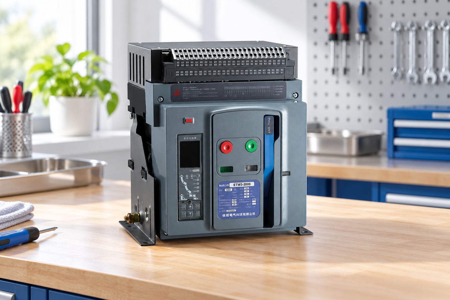
The SUTON ETW3 product page introduces the family but does not provide every service instruction for every ordered configuration. Request the exact maintenance manual and available service parts before the panel is delivered. If a legacy unit lacks documentation, identify it through approved records and the responsible supplier before attempting internal work.
Separate calendar, usage and event triggers
A calendar interval provides a planned opportunity to check equipment even when no fault has been reported. An operating-count trigger addresses wear caused by repeated mechanical operations. An event trigger responds to an interruption, overheating, contamination, abnormal noise or an unexplained trip. A complete program considers all three, and uses the most relevant trigger for the next inspection.
Frequent operation in a harsh environment can justify an earlier review than infrequent service in a controlled room. Conversely, an essential standby breaker still requires checks even if its operating count is low. Agree the interval with the manufacturer and the responsible maintenance engineer. Do not extend it solely because the breaker has not tripped; the absence of a trip is not proof that its opening mechanism or protective circuit will work when required.
Use a condition-based maintenance scope
| Trigger or observation | Planning response | Evidence to retain |
|---|---|---|
| Scheduled service point | Apply the exact manual’s isolated inspection and test scope | Asset identity, checklist revision and results |
| Frequent operations | Review mechanism wear and the manufacturer’s count limits | Operation counter and service history |
| Fault interruption | Assess the interruption duty and required post-fault examination | Fault record, trip data and inspection decision |
| Heat, odor or discoloration | Investigate the cause under a controlled safe-work plan | Load conditions, photographs and corrective action |
| Dust, moisture or corrosion | Correct the environment and review affected components | Exposure conditions and inspection findings |
| Changed settings or accessories | Check the revised configuration and affected protective tests | Approved change and final verified settings |
This qualitative table is a planning tool. It intentionally supplies no universal service months, contact-wear limits or lubricant specifications; those must come from the exact device instructions.
Plan an outage and control every energy source
Inspection inside a breaker or compartment requires an approved safe electrical condition. Identify primary supplies, control supplies, possible backfeed and stored mechanical energy. A main contact indicator showing open does not establish isolation of adjacent busbars or independently supplied control circuits. Define the work boundary and secure the equipment against unintended operation.
The HSE safe working practices guidance addresses planning for electrical work. Apply the relevant local procedure with competent personnel, suitable instruments and the correct equipment instructions. This article does not provide a live maintenance method. If the required outage cannot be obtained, change the service plan rather than assuming that a withdrawn breaker makes every compartment part safe.
Inspect the enclosure, insulation and environment
Look for moisture paths, corrosion, dust deposits, damaged barriers, tracking, heat damage and missing hardware. Record the location and extent of an observation rather than describing the whole breaker as “dirty.” Investigate the source of contamination, because cleaning alone may leave the condition that caused it unchanged. Confirm that the room ventilation and enclosure arrangement support the actual service environment.
Use only the cleaning methods authorized by the manufacturer. Solvents, compressed air, abrasives and cleaning fluids can affect insulation or drive contamination into mechanisms if used indiscriminately. A visually clean assembly is not proof of adequate insulation condition. Any specified insulation test must use the approved test arrangement, with electronic equipment and accessories treated as the instructions require.
Inspect contacts and arc-control components within allowed access
Contact and arc-chute examination should follow the exact inspection procedure. Look for the documented wear indicators, damaged components and evidence of abnormal interruption duty. Do not infer remaining contact life from a general online photograph or apply another model’s wear dimensions. Keep the observed condition tied to the asset identity and the relevant manual limit.
A serious interruption may create inspection or replacement requirements even when the breaker can still be operated mechanically. Ask the manufacturer what evidence is required after the recorded fault duty. Filing, dressing or modifying a contact can alter its geometry and performance; do not perform such work without explicit model-specific instructions. Replacement parts must have the approved identification and installation method.
Check the operating mechanism and releases
Review the charging mechanism, indication, opening response and closing behavior with the permitted isolated test arrangement. Check for binding, damaged components or inconsistent response. Record the operating count if available and compare it with the maintenance history. A breaker that closes locally may still have a failed remote release or an incorrect permissive.
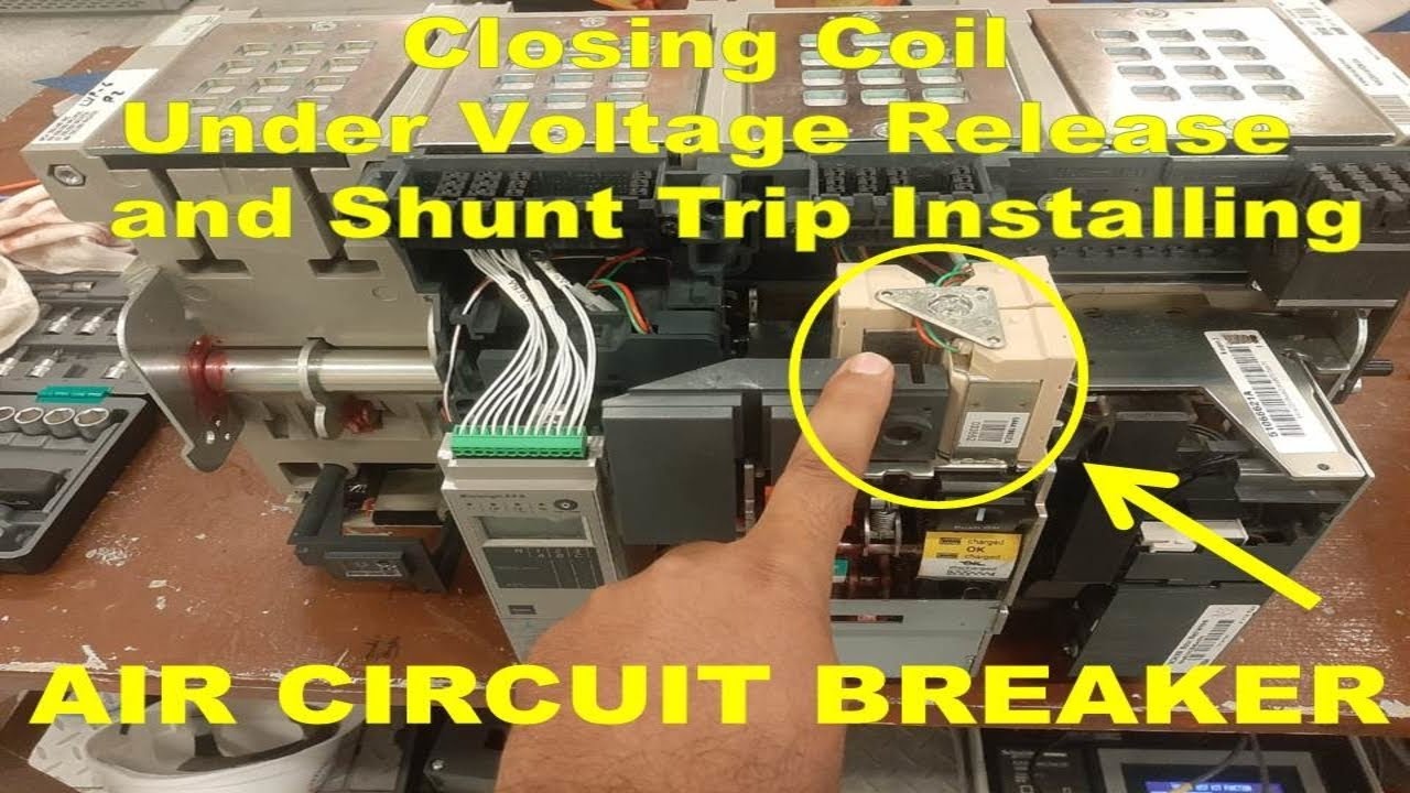
Lubrication is a model-specific activity. The wrong material or excessive application can attract dirt or affect components intended to remain dry. Use the specified lubricant at the specified locations only. The ACB control-release guide explains the distinct purposes of closing, opening and undervoltage releases; each relevant function requires its own response check.
Include the withdrawable cradle and disconnects
For a drawout unit, the cradle, primary disconnects, shutters, position indications and interlocks are part of the service scope. Inspect the authorized areas for wear, alignment or damage, and verify the permitted position behavior. Do not treat the removable breaker alone as the entire maintained asset. A healthy mechanism cannot compensate for damaged mating connections.
Record the approved breaker-to-cradle pairing and any changes made during service. Include secondary plugs and control connections where accessible under the procedure. The fixed versus drawout comparison helps explain why a withdrawable design has additional maintenance interfaces. Unexpected resistance during insertion or racking is a reason to investigate, not to defeat an interlock.
Select tests that answer a stated maintenance question
Contact resistance, insulation checks, mechanical operation and protective-function testing address different aspects of condition. Specify why each test is needed and what constitutes acceptance. A contact-resistance reading alone cannot prove that the trip unit will detect a fault, and a secondary-injection result cannot demonstrate the entire primary sensing path.
Use the manufacturer’s method and a calibrated instrument suited to the equipment. The Electrical Installation Guide maintenance overview provides background on maintenance scope; model limits remain controlling. Compare readings with the baseline and prior results under comparable test conditions. Unexpected variation should trigger investigation rather than an automatic pass because one number is below an informal internet threshold.
Check settings and preserve the approved configuration
Record protective settings before and after maintenance. Verify that sensor configuration, enabled functions and accessory settings match the approved study. If replacement or testing requires a temporary setting, document the change and its restoration. An accidental retained test setting can leave a mechanically healthy breaker unsuitable for its actual duty.
Configuration changes require authorization and an assessment of their effects on conductor protection and selectivity. Do not increase pickup to hide nuisance trips. Check event records, load conditions and sensing arrangements first. The frame and sensor rating guide helps avoid confusing the mechanical frame rating with the current reference used by the protective function.
Make the return-to-service decision explicit
Before restoration, confirm that tools and test connections are removed, barriers and covers are restored, settings are correct and applicable function tests have passed. Record unresolved observations and decide whether they prevent service. A signature beside “maintenance complete” should refer to actual results, not only to an elapsed work order.
The IEC 60947-2 standard page establishes the circuit-breaker product context, but ordinary maintenance does not reproduce all product certification tests. Define what the service team has actually verified and what remains dependent on the original design. Keep the final condition report, replaced part codes and next inspection trigger available to the operating team.
Plan support and spares before the next outage
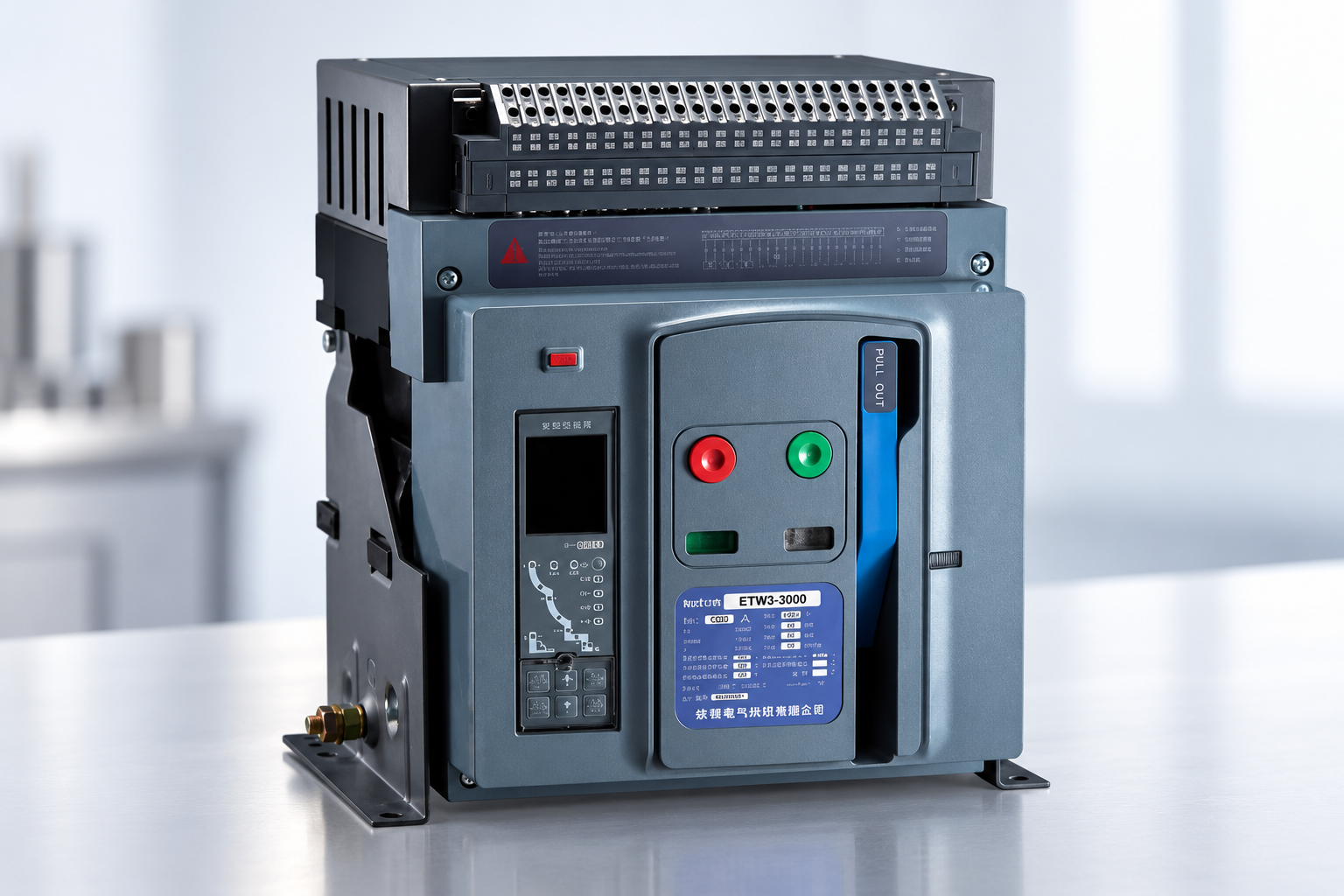
Provide SUTON with the exact ETW3 order code, trip-unit details, photographs of the original asset and the maintenance question. Request approved instructions, applicable replacement components and any required service support. Include the interruption or operating history when investigating a fault. A clear technical inquiry is more useful than asking for a generic annual checklist.
For essential supplies, plan a compatible spare strategy and the time needed to verify a replacement configuration. Use the breaker types overview as broader context. The practical objective is an achievable service program that preserves protection and availability, with intervals justified by manufacturer guidance and observed duty.
Frequently asked questions
Should every ACB be serviced once a year?
No universal interval applies. Follow the exact manual and consider duty, operating count, environment and significant events.
Does a successful closing operation prove the breaker is healthy?
No. Protective response, opening releases, insulation, connections and relevant interlocks also require appropriate checks.
Can maintenance settings remain after testing?
Only the approved operating configuration should remain. Record temporary changes and verify restoration before service.
Educational video: protective and control functions
Closing Coil, Undervoltage Release, and Shunt Trip Installing of ACB | Tripping Coil | Closing Coil by Evergreen Electrical. This educational demonstration supports the control-function checks discussed above; it is not an ETW3-specific installation or live-work procedure.