Choosing a 2 pole vs 4 pole DC breaker for a PV system starts with the approved circuit arrangement, not the number printed in a catalogue title. The required poles depend on the maximum design voltage, conductor switching requirements, grounding arrangement and manufacturer's tested configuration. A four-pole device is not automatically suitable for twice the voltage, and a two-pole device is not automatically unsuitable for a particular PV circuit. Compare the declared DC rating for the exact wiring arrangement, then confirm current, fault duty, isolation function and installation conditions before ordering.
What a pole means in this comparison
A pole is a switching path within the complete device. It is not a promise of a fixed voltage increment that can be added without qualification. A multi-pole breaker can have several approved configurations, or only one. The number of handles, terminal openings and external links may help identify a configuration, but its acceptance depends on documented performance. Buyers should distinguish physical pole count from the number of conductors switched and from the number of interruption paths assigned to each conductor.
This matters because a quotation often reduces the product to voltage, current and pole count. Those fields are useful identifiers, but they omit how the voltage is distributed across the intended switching arrangement. The same shorthand can conceal different source/load restrictions or grounding assumptions. Request the full diagram and applicable rating table rather than comparing catalogue fragments. Keep the exact order code visible throughout the review so that a proposed alternative cannot silently inherit another unit's approval.
Start with the PV system voltage
Establish the maximum array voltage using actual module data, series count and the project's accepted temperature correction method. Nominal system voltage and maximum-power voltage are not substitutes for that calculation. Document the inputs and their revision dates. If the module type or string length changes, review the result again. A breaker selected for an earlier design may no longer have adequate operational voltage capability even when the expected normal current remains almost unchanged.
Next, identify the manufacturer's declared operational DC voltage for the proposed pole arrangement. Do not use insulation voltage as though it were an interruption rating. Do not add pole ratings arithmetically unless the exact series arrangement is approved. The guide to PV string voltage and DC breaker rating explains the voltage worksheet separately. The objective here is to connect that verified design result to a documented switching configuration, leaving a clear evidence trail.
Grounding changes the configuration question
A PV circuit may have different grounding or functional earthing arrangements depending on the inverter, system design and applicable requirements. Those arrangements affect which conductors must be switched and how faults are evaluated. Never select a two-pole or four-pole layout by assuming that every installation has the same grounded conductor. Record the actual system arrangement and have the responsible designer confirm the protection and disconnection requirements before the supplier recommends a product.
Ground-fault conditions deserve explicit attention. A simplified normal-operation drawing may not show the voltage stress that matters during a fault. Ask whether the declared breaker configuration covers the actual arrangement and relevant fault scenarios. If the supplier provides several diagrams, mark the one being proposed and retain its conditions. A diagram with a familiar number of poles is not enough if it belongs to a different grounding arrangement or excludes the project's operating conditions.
Series connections require product approval
Some DC switching arrangements use poles in series to obtain a stated capability. That possibility does not authorize arbitrary external links. The location, conductor size, link type and terminal arrangement must follow the applicable instructions. Incorrect links can defeat the intended arrangement or create unacceptable heating. Treat link accessories and their installation requirements as part of the ordered configuration rather than an item for the installer to improvise after delivery.
Do not divide one multi-pole device into unrelated circuits unless that use is expressly supported. Common operation, internal clearances and tested performance belong to the complete device. A buyer seeking two independent protective functions should state that requirement directly. The supplier can then propose suitable equipment and documentation. Reusing spare poles merely because they are physically available can create a configuration that no submitted rating actually covers, undermining an otherwise careful specification.
Build a configuration comparison sheet
| Comparison item | Two-pole proposal | Four-pole proposal |
|---|---|---|
| Identity | Record exact order code | Record exact order code |
| Voltage | Cite declared DC rating for proposed diagram | Cite declared DC rating for proposed diagram |
| Grounding | Confirm matching system arrangement | Confirm matching system arrangement |
| Connections | List approved links and terminal requirements | List approved links and terminal requirements |
| Fault duty | Compare applicable DC breaking capacity | Compare applicable DC breaking capacity |
| Integration | Check dimensions, cables and access | Check dimensions, cables and access |
Complete the sheet for each offer using the same project inputs. Where a cell cannot be answered, record the evidence gap rather than inserting a guessed value. A useful comparison may show that both pole counts could work under different approved arrangements, or that only one proposal satisfies the design. The purpose is to identify an accepted configuration and its boundaries. It is not to establish a universal winner between two-pole and four-pole products.
Check current and fault capability independently
After voltage and configuration are resolved, verify continuous current, trip characteristics and the applicable DC breaking capacity. The current rating does not become larger because the device has more poles. Likewise, adding poles does not automatically establish an adequate fault rating. Review all contributing sources, including parallel strings, storage or other equipment where relevant. State the available fault duty at the proposed location and request a matching declaration for the complete arrangement.
Thermal conditions also matter. Pole loading, adjacent devices, enclosure layout and internal air temperature can affect usable current according to manufacturer instructions. A four-pole arrangement may occupy more panel space and require different connection routing, but size alone does not determine thermal suitability. Include the enclosure conditions in the selection request. A product that meets a catalogue rating under one reference condition may need a different application assessment inside a crowded outdoor combiner enclosure.
Review the actual SUTON product evidence
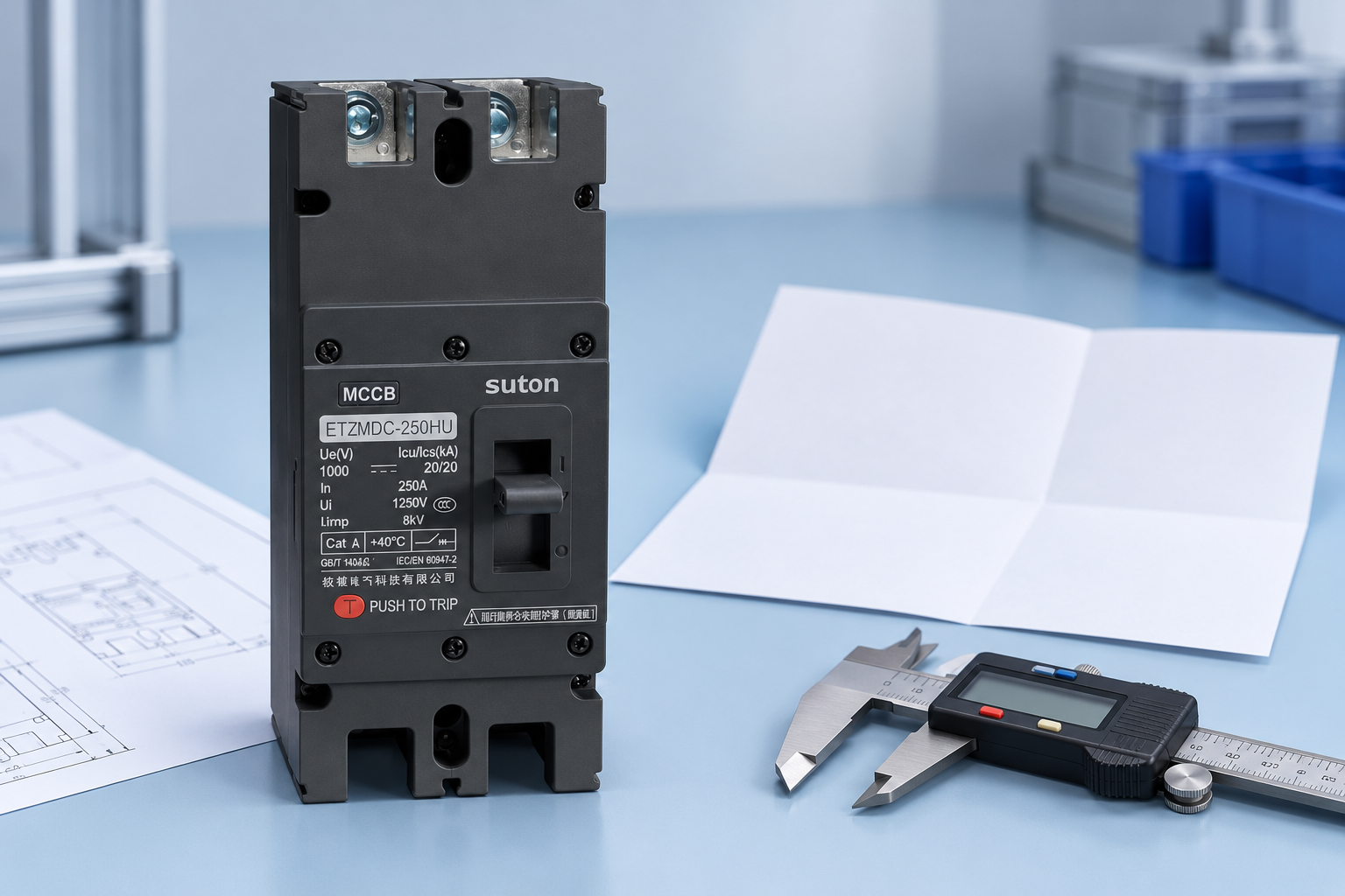
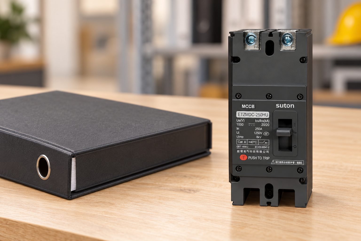
The SUTON ETZM PV molded-case DC breaker is a relevant product family for a PV protection enquiry. The reference images in this article show the actual exterior supplied by the website. They are identity illustrations, not drawings of every pole option or evidence that the pictured unit has any particular series configuration. Ask for the model and arrangement appropriate to the project instead of ordering from an illustrative photograph.
A complete enquiry should include maximum design voltage, design current, available fault contribution, grounding, circuit location and enclosure conditions. Request the exact terminal diagram, required links, tightening instructions and dimensional drawing. If a four-pole alternative is proposed to replace a two-pole selection, review all of those items again. The change can affect wiring space, accessories, maintenance access and documentation even when the commercial description appears to be a straightforward upgrade.
Avoid misleading shortcuts in drawings
Do not write “two poles equal one positive and one negative” as a universal rule. Do not write “four poles equal two strings” without explicit product approval. Those statements can be wrong for the intended interruption arrangement. Draw the actual device boundaries and approved connections, identify the source and load sides where required, and use the manufacturer's terminal numbering. A controlled drawing lets a second reviewer check the design without reconstructing assumptions from a catalogue screenshot.
The IET guidance on PV DC switch-disconnector configuration illustrates why configuration-specific declarations matter. Its switching-device discussion must not be copied as a breaker installation instruction. The national laboratory overview of PV DC systems supplies wider system context. Use these sources to frame questions; obtain the selected breaker's own current documents to answer them for the order.
Acceptance and commissioning records
At receiving inspection, compare the delivered order code, pole count, terminal layout and accessories with the approved submittal. Check that required links and labels are included and that instructions match the delivered revision. Resolve discrepancies before installation. During commissioning, qualified personnel should verify the actual wiring against the approved drawing under the project's safety procedure. Do not experimentally test interruption by creating a fault or changing connections while a PV source remains energized.
Retain the comparison sheet, final diagram and supplier clarification together. These records become valuable when an inverter is changed, strings are added or maintenance staff replace a damaged breaker. The guide to DC breaker polarity addresses a separate direction-of-current check, while the overall solar PV breaker selection guide brings the requirements together. A defensible selection passes each check rather than relying on pole count to answer every question.
Frequently asked questions
Is a four-pole DC breaker always better than a two-pole breaker?
No. Select the configuration documented for the system's voltage, grounding, conductor switching and fault duty. More poles can add space and connection requirements without resolving an unsuitable rating. Compare the complete approved arrangement and its installation conditions rather than treating pole count as a quality ranking.
Can I multiply one pole's voltage rating by four?
Only use a combined voltage capability expressly declared for the exact series arrangement by the manufacturer. Pole count alone does not establish an interruption rating, and insulation voltage is not an alternative operational DC rating. Keep the approved wiring diagram with the purchase and installation records.
Can unused poles protect a second PV string?
Do not assume they can. A multi-pole device's common operation and tested arrangement may require those poles for one circuit. Independent circuits need equipment explicitly suitable for that use. Ask the manufacturer and responsible designer to confirm the proposed arrangement before ordering or wiring it.
Educational video
How do solar panels work? – Richard Komp by TED-Ed. This independent TED-Ed lesson explains how photovoltaic cells generate electricity. It supports the PV-source context; it does not approve breaker wiring, sizing, thermal limits or a maintenance isolation procedure.