Neutral busbar sizing for nonlinear loads starts with the expected neutral current, not an automatic percentage of the phase conductor. In a three-phase, four-wire distribution system, load imbalance creates fundamental-frequency neutral current, while some harmonic components from electronic loads can add in the neutral. Select the complete neutral path for its calculated duty, then verify thermal performance, terminals, protection and the assembly configuration. A larger metal cross-section alone does not prove an enclosed distribution assembly is suitable. This guide explains what buyers and panel engineers should collect before specifying a neutral arrangement for an LV panel.
Establish which loads actually use the neutral
Begin with the circuit diagram. Identify every outgoing circuit connected between a phase and neutral and separate it from three-phase loads that do not use the neutral during normal operation. An installation containing many electronic devices is not automatically one particular harmonic case. The input circuit, filtering, operating mode and mix of equipment affect the current waveform. An equipment label showing watts or amperes is therefore only the start of the assessment.
Prepare a load schedule that names each circuit, its phase allocation, operating hours and expected simultaneous demand. Include future circuits that the project is intended to support. A distribution board feeding office electronics, LED lighting and small single-phase power supplies may have a different neutral duty from a board feeding balanced three-phase motors. Keep these cases separate rather than applying a blanket neutral allowance to both.
The neutral and protective earth have different functions. Do not treat the protective conductor or enclosure as an alternative neutral return path. The earthing arrangement, permitted neutral switching and bonding locations must follow the project design and applicable installation rules. A purchaser should obtain an approved single-line diagram rather than infer these functions from the number of visible terminals in a catalog photograph.
Separate imbalance from harmonic current
For sinusoidal balanced phase currents separated by 120 electrical degrees, the fundamental components cancel at the neutral junction. When their magnitudes or phase angles differ, a residual remains. Adding the three phase RMS readings arithmetically does not calculate this residual. Fundamental-frequency analysis requires phase information, while a practical survey needs instruments capable of capturing the actual waveform and operating conditions.
Nonlinear single-phase loads can draw distorted current. Under symmetrical conditions, triplen components such as the third harmonic can be in phase across the three supply phases, so their neutral contributions add rather than cancel. This is why balancing the fundamental load does not guarantee a lightly loaded neutral. Conversely, a harmonic-rich load description does not justify assuming the same spectrum for every circuit.
NIST research on spectrum tracking explains why nonlinear loads complicate power-system measurements and why identifying harmonic components matters. For sizing, request the relevant equipment spectrum or a representative survey; a single total harmonic distortion percentage does not identify which components enter the shared neutral.
Calculate a documented neutral design current
Use the instantaneous relationship iN(t) = -(iA(t) + iB(t) + iC(t)) at the neutral junction, with consistent current directions. An engineer can sum waveforms directly or evaluate each frequency component as a phasor before combining different frequencies by RMS. These calculations need actual circuit assumptions and phase relationships. A spreadsheet that uses phase current alone without explaining the waveform cannot establish the neutral design duty.
Consider an explicitly simplified example: each phase supplies 100 A fundamental current and a 30 A third-harmonic component. Assume the fundamentals are perfectly balanced, the three third-harmonic contributions are aligned, and there are no other components. The fundamental neutral current is zero, while third-harmonic neutral current is 3 × 30 = 90 A. The phase RMS current is approximately square root of (100 squared + 30 squared), or 104.4 A. These are illustrative inputs, not a SUTON product rating.
If the assumed third harmonic increases to 50 A per phase, its neutral contribution becomes 150 A, while each phase RMS is approximately 111.8 A under the same simplified assumptions. This shows why neutral current can exceed phase RMS current. Real installations need additional harmonic orders, imbalance, diversity, waveform phase angles and changing operating modes assessed together. Neither example selects a busbar size in square millimetres.
For the overall construction context, read the busbar system guide for panel builders. Keep the neutral analysis attached to that assembly record so the selected arrangement, supporting evidence and delivered order remain consistent.
Match current duty to assembly verification
Translate the calculated duty into an assembly specification. State the phase and neutral currents expected simultaneously, the harmonic assumptions, the ambient conditions and the enclosure arrangement. The neutral path may include several bars, joints, connectors and terminals; every part must support the required duty. A full-size bar can still be paired with a limiting terminal or an unsuitable connection arrangement.
IEC 61439-1 provides the general framework for LV assembly construction and verification and is used with the relevant assembly-specific part. Its public description also highlights group rated current and temperature-rise verification. Ask the assembly manufacturer to identify the applicable standard and demonstrate that the offered configuration matches the declared service conditions. Do not treat a general standards reference as proof for an individual order.
| Review item | Input to collect | Acceptance evidence |
|---|---|---|
| Load identity | Phase-to-neutral circuits and simultaneous duty | Approved circuit and load schedule |
| Waveform | Relevant harmonic magnitudes and phase relationships | Equipment data or representative survey |
| Neutral duty | Calculated RMS current and operating envelope | Documented design assumptions |
| Thermal design | Simultaneous phase and neutral loading | Matching assembly verification |
| Connections | Complete neutral route and terminal compatibility | Order-specific drawing and instructions |
| Protection | Earthing and neutral switching arrangement | Coordinated project design |
The table is a project review checklist rather than a conductor sizing chart. The required thermal and construction evidence depends on the applicable assembly standard and the offered design. For the broader loading assessment, use the related busbar current rating calculation guide without substituting its preliminary calculations for neutral-specific verification.
Check joints, terminals and the complete neutral path
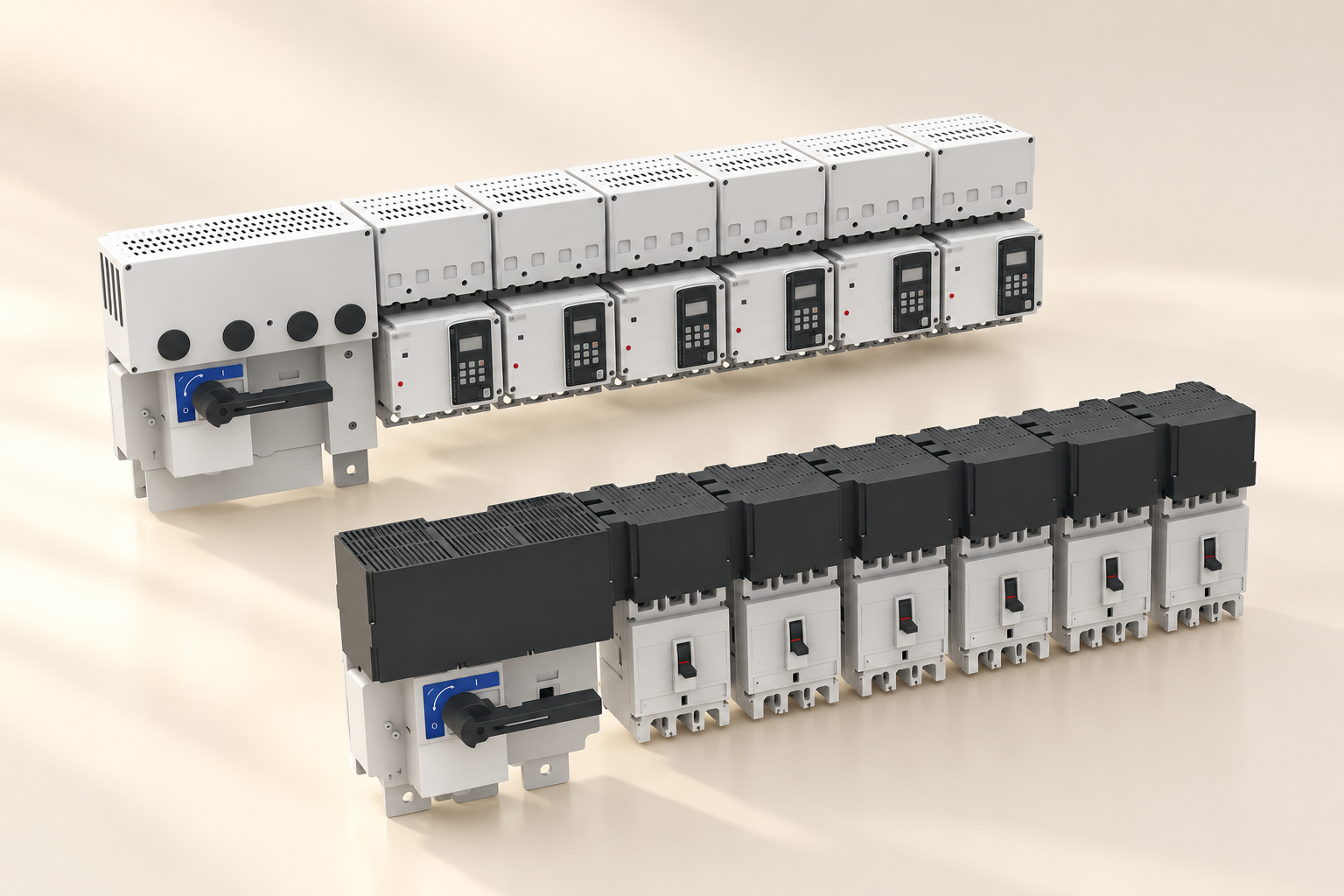
Review the neutral route from the incoming connection to every outgoing circuit. Confirm terminal conductor compatibility, connection capacity, permitted parallel connections and identification. Ask whether the offered neutral arrangement changes when outgoing module quantity or enclosure size changes. The drawing should identify the actual configuration supplied, including any separate neutral bars that are not visible in the catalog image.
Where a neutral is switched, its operation must fit the system and equipment design. A neutral opening unexpectedly while phases remain connected can create hazardous voltage conditions in some four-wire systems. Do not add a fuse, switch or breaker to the neutral as an informal remedy for an undersized bar. The protection and switching scheme requires coordinated engineering review, including its behavior during abnormal conditions.
Joint quality matters because current passes through interfaces as well as solid metal. Obtain approved tightening instructions, compatible conductor materials and installation requirements. Do not invent a torque value from bolt size or recommend retightening energized equipment. Inspection and testing must follow the manufacturer's procedures and the site's safe isolation process, with appropriate competence and authorization.
Measure representative operating conditions
A useful survey captures phase and neutral currents together across representative load cycles. Record the instrument, sensor orientation, measurement range, sampling or harmonic capability and operating state. Note which circuits were active, whether standby supplies were carrying load and whether occupancy or production was typical. A brief measurement during a quiet period can miss the design condition.
True-RMS capability is necessary for many distorted-current measurements, but the label alone does not establish adequate bandwidth or accuracy for every waveform. Check the instrument specification and the harmonics being evaluated. If a survey reports a neutral current higher than expected, verify the measurement arrangement before changing the design. Incorrect sensor placement or undocumented parallel paths can produce misleading conclusions.
Compare measured duty with the documented design case and retain the result with the panel records. If future loads are uncertain, specify an agreed operating envelope and a review trigger. This is more useful than promising unlimited spare capacity. Changes to power supplies, lighting controls or circuit allocation can require reassessment even when the connected power total appears unchanged.
Review the actual SUTON product arrangement
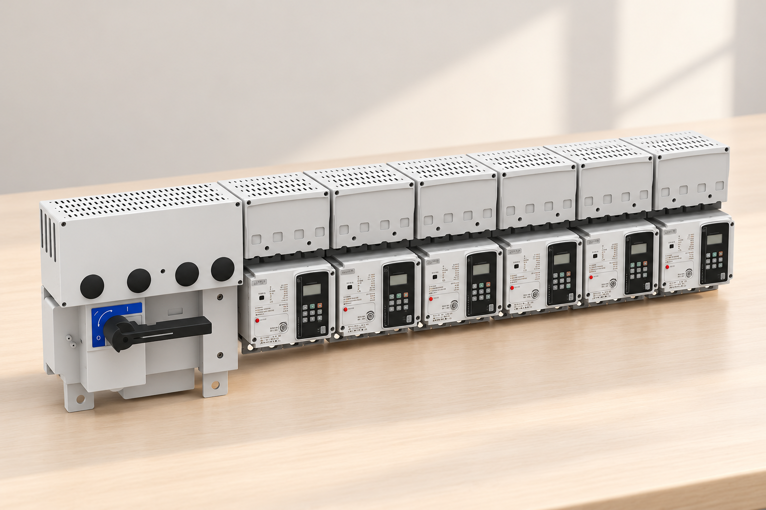
The SUTON ETFZX enclosed busbar system is a product reference for discussing enclosed distribution construction. The illustrations show its exterior only. They do not identify an internal neutral route, prove a conductor material or establish a neutral current rating. Request the order-specific drawing and declared characteristics for the arrangement being considered.
For a quotation, provide the supply system, circuit schedule, calculated phase and neutral duty, expected harmonic spectrum, ambient range and installation location. Include the required documentation and acceptance process. Ask the supplier to state any limitations explicitly, so commercial comparisons use equivalent scope rather than matching only a nominal main current.
Coordinate this review with copper versus aluminum busbar selection and short-circuit withstand verification. Neutral thermal adequacy does not independently establish fault performance, material compatibility or insulation coordination. Each question needs its own evidence, tied to the same final assembly identity.
Frequently asked questions
Must the neutral busbar always be larger than the phase busbars?
No. Its required capability depends on calculated neutral current, harmonics, imbalance, installation conditions and the verified assembly design. Some projects need enhanced neutral capability; others do not. Choose a documented duty and compatible verified configuration rather than applying an automatic larger-or-smaller rule.
Does balancing single-phase loads eliminate neutral heating?
Balancing can reduce fundamental-frequency imbalance, but some harmonic components can still add in the neutral. Examine the load spectra and simultaneous phase and neutral currents. A balanced set of phase RMS readings alone does not demonstrate cancellation or establish the neutral thermal margin.
Can a product photo confirm the neutral rating?
No. A closed housing does not show the complete neutral path, joint details or thermal performance. Obtain the order-specific circuit diagram, conductor and terminal details, declared ratings and applicable verification evidence before accepting the arrangement for the project.
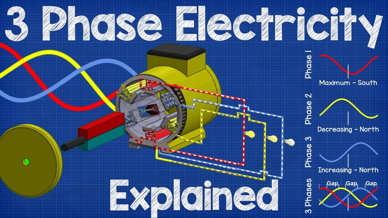
Educational video
How Three Phase Electricity works – The basics explained by The Engineering Mindset. This educational video explains three-phase currents as background for neutral-current analysis. It does not establish a harmonic spectrum or approve a neutral busbar size.