ACB protection settings determine how an installed air circuit breaker responds to overload, short-circuit and ground-fault conditions. Common electronic trip units use long-time, short-time, instantaneous and ground-fault functions, but the available controls and ranges are model-specific. Start with the fault, load and coordination study, then confirm the frame, sensor and trip unit actually installed. Set each pickup and delay against conductor and switchboard limits, record the approved values, and verify them with the manufacturer’s test method. Do not copy a settings chart from a different breaker.
Start with the circuit study and the installed trip unit
An ACB protection setting is a decision about what current the installed device should tolerate, detect and interrupt in a specific distribution system. It is not a universal factory number. Collect the single-line diagram, transformer and generator data, maximum and minimum fault-current calculations, conductor ratings, load profile, downstream protective devices and the selectivity target. Confirm the ACB frame, sensor or rating module, electronic trip-unit model and firmware from the actual installed assembly before reading a settings table.
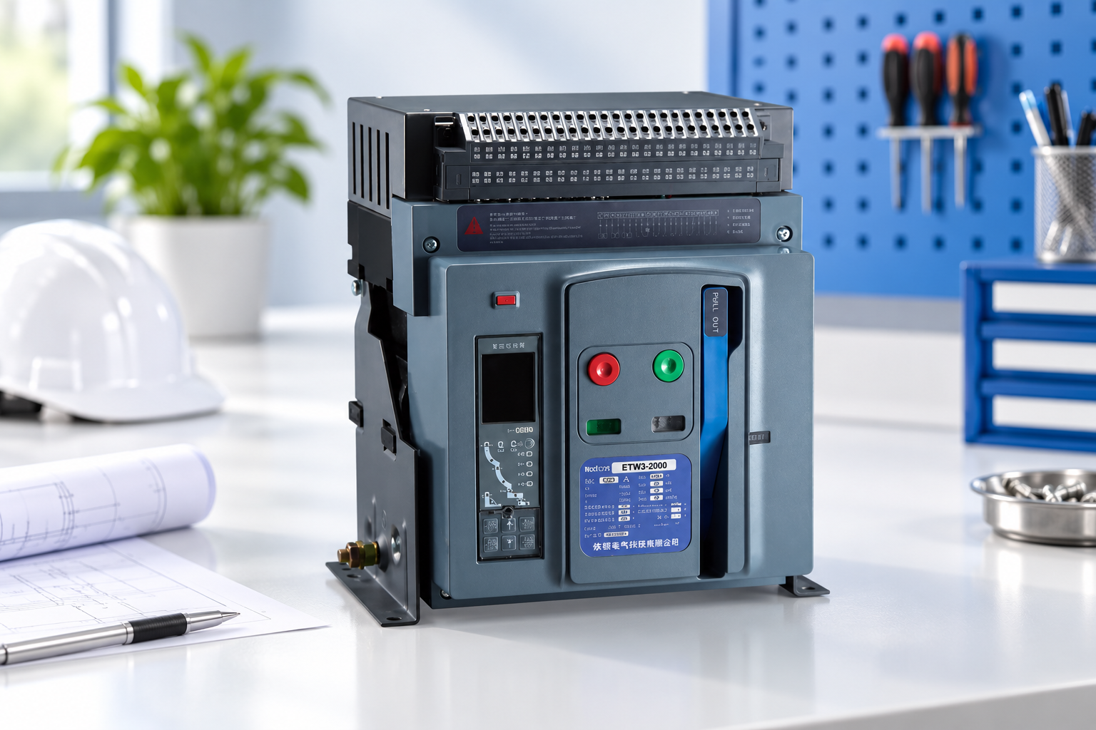
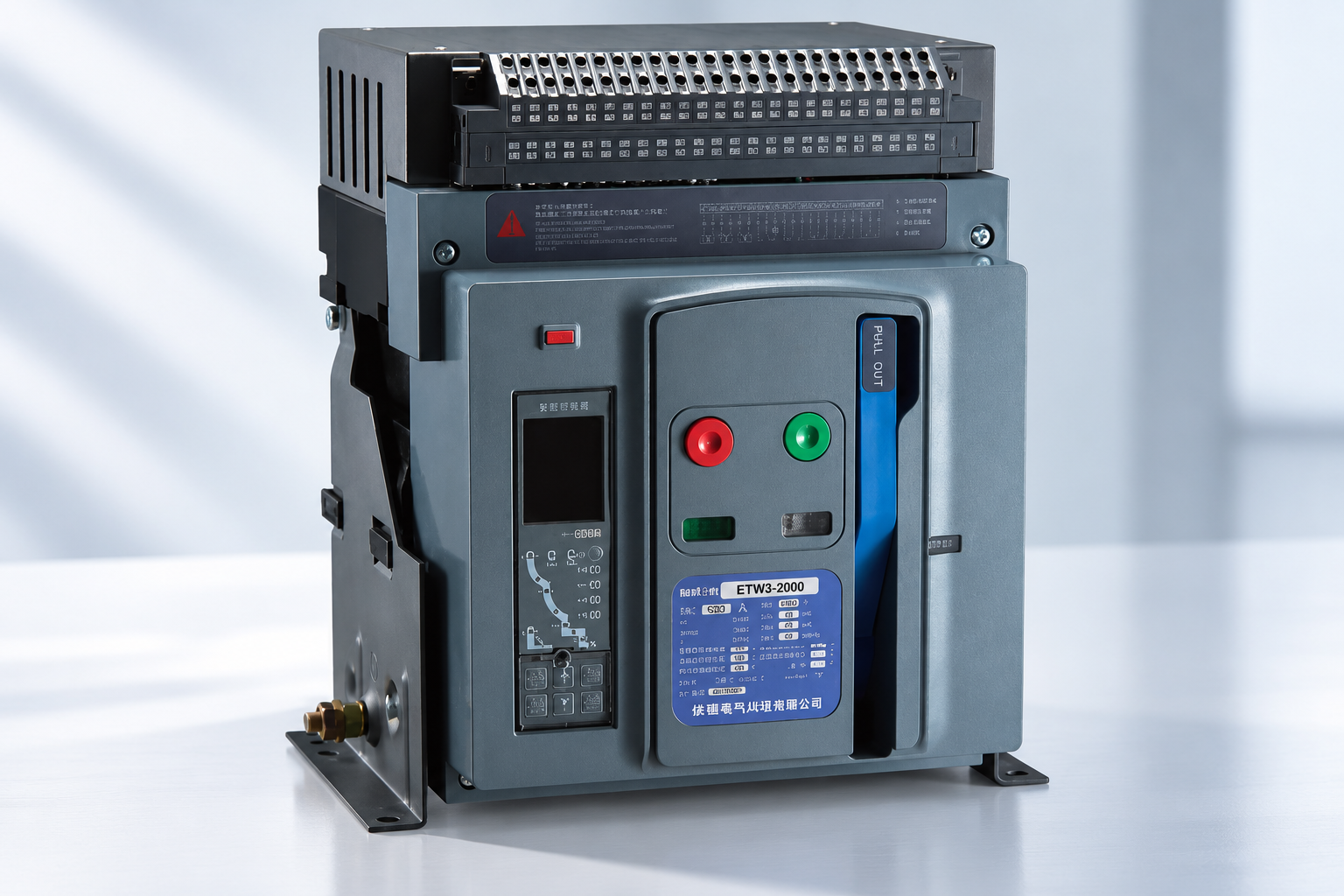
The SUTON ETW3 product page identifies a real family and lists model-level electrical information, but the public page does not publish a complete trip-unit setting guide for every configuration. Request the exact manual and approved setting range for the ordered code. Do not apply values from another manufacturer or frame merely because its front panel looks similar. The frame-versus-sensor guide explains why those two references must be recorded separately.
Read L, S, I and G as distinct protective functions
Electronic trip units commonly describe long-time (L), short-time (S), instantaneous (I) and ground-fault (G) functions. The available functions and their exact names depend on the installed trip unit. Some models offer only a subset or add separate neutral and advanced features. A setting sheet should show whether each function is enabled, its pickup reference, its delay or curve, and the study that supports it. The IEC 60947-2 product-standard page provides the circuit-breaker context, not a substitute for a project coordination study.
| Function | Question it answers | Evidence before setting |
|---|---|---|
| Long-time (L) | When should sustained overload open the breaker? | Load and conductor thermal limits |
| Short-time (S) | How should a delayed short-circuit stage coordinate? | Fault study, withstand and downstream curves |
| Instantaneous (I) | When is no intentional delay appropriate? | Maximum fault level and selectivity limits |
| Ground-fault (G) | How is a measured earth-fault condition handled? | Grounding system, sensors and coordination |
| Neutral / special functions | What additional path or mode is protected? | Exact trip-unit manual and wiring diagram |
This qualitative table is a planning checklist. It does not assert that a particular ETW3 model includes every function or adjustable range.
Set long-time pickup around the actual continuous duty
Long-time pickup must protect the conductors and equipment while carrying the intended continuous load and expected operating variations. Record the reference current used by the trip unit, the selected pickup and the long-time delay or curve. Check busbars, terminal temperature, enclosure conditions and ambient correction as well as cable capacity. A frame marked for a higher current does not authorize a higher long-time setting when the conductors or switchboard are rated lower.
Compare normal load, foreseeable growth, motor starting and temporary operating modes. An unnecessarily low pickup can interrupt a legitimate load; an unjustifiably high pickup can permit prolonged overheating. Do not solve nuisance operations by raising the dial before investigating actual current and the event record. Keep the relevant load calculation and trip curve beside the approved value, so a later engineer can understand the reason for it.
Coordinate short-time pickup and delay
Short-time protection can permit a downstream device to clear a fault while an upstream ACB waits for a defined interval. That delay is not free: the upstream breaker, busbars and conductors must withstand the current for the time involved. Compare time-current curves with tolerances, breaker short-time withstand, minimum available fault current and downstream clearing times. A curve that appears separate on a simplified plot can still conflict when actual tolerances or source modes are considered.
Document the reason for each pickup and delay as a pair. A change to either can affect selectivity, thermal duty and incident energy. The IEC technical report on overcurrent selectivity frames selectivity as a system assessment. If a scheme uses zone-selective interlocking, check the exact model’s capability and wiring rather than assuming a generic S setting implies it; the model-specific interlocking documentation is required for that separate choice.
Check instantaneous protection against the fault study
Instantaneous operation clears high-current faults without an intentional delay, but a low upstream threshold can defeat downstream selectivity. Conversely, disabling or raising it may be unacceptable if the breaker or assembly cannot tolerate a delayed fault. The permissible setting depends on the manufacturer’s trip-unit range, short-time withstand, maximum prospective fault current, downstream devices and applicable project rules. Never copy an “instantaneous off” recommendation without checking those conditions.
Review both utility and generator supply. Generator-fed fault current may be lower and decay differently, so a threshold suitable under the utility may fail to detect some faults promptly on backup supply. Record the study’s assumptions and the as-left value. The breaking-capacity guide explains why interruption duty is a separate rating from a trip pickup.
Ground-fault and neutral settings need a return-path drawing
Ground-fault protection depends on how current is measured, the system grounding arrangement and any external neutral sensor. A three-pole breaker on a four-wire system may need a model-specific neutral measurement arrangement; a four-pole breaker may have different options. Verify sensor orientation, wiring, transformer ratio, neutral treatment and the function’s enable state before applying a ground-fault pickup. Do not infer these from the pole count or a product photograph.
Compare downstream residual-current or ground-fault devices so the intended device operates first. Source transfers and parallel paths can change return currents. A site with a generator, UPS or bus tie should be evaluated in each credible operating state. If nuisance trips occur, investigate the physical neutral/earth arrangement and actual leakage instead of immediately increasing the threshold.
Use a controlled settings sheet
List the exact device and trip-unit codes, sensor identification, every active function, current references, pickup values, delays, curve selections, communications or special modes, date, study revision and approving engineer. Record any factory defaults separately from the values authorized for service. A quotation, a drawing and a display menu can each contain different numbers if revisions drift; one signed sheet must identify the final authority.
If the interface uses menus, save an export or photographs of each relevant page. If it uses dials, record positions and scale definitions from the manual. Tag the board with the study revision, not just a current value. An operator should not be able to change a protective setting informally to clear an alarm. Changes to load, transformer, source, cables or downstream breakers should trigger an engineering review of affected settings.
Verify with the manufacturer-approved test method
Before energization, confirm wiring, trip-unit supply, indications, protection enable state and settings readback against the approved study. Apply primary or secondary injection only where the manufacturer and project test plan specify it; each method proves different parts of the sensing and trip chain. Record the instrument, calibration status, test connection, injected values, trip times, outcome and as-left settings. A display self-test or front-panel button cannot alone prove every current path and breaker mechanism.
The HSE electrical safety guidance reinforces isolation and competent work. Follow local rules, site permits and the exact ETW3 documentation. If a test result is outside tolerance, investigate the wiring, sensor and instrument setup before changing protective values. Retest after corrective action and retain both the failed and passing records.
Review operational consequences before signing off
A protective setting affects both safety and continuity. Simulate or study likely feeder faults, bus faults, earth faults, motor starts, temporary overloads and source transfers. Confirm which breaker should trip in each case and which equipment remains energized. Do not claim that one LSIG sheet eliminates arc-flash risk; the complete incident-energy and safe-work assessment remains necessary. The IET guide to protective and switching devices distinguishes protection from ordinary operational switching.
At handover, give operations staff a clear event-response process: record the indicated function and time before reset, isolate unsafe equipment, and escalate repeat or unexplained trips. Keep the settings sheet, coordination curves and trip logs together. This turns a future trip into useful evidence rather than an invitation to move controls by trial and error.
Procurement questions for the exact ETW3 offer
Ask for the full breaker and trip-unit model codes, frame and sensor references, poles, neutral arrangement, available L/S/I/G functions, permitted adjustment ranges, interruption and short-time ratings, accessory list, communications options and current manuals. Ask whether any feature is optional, factory-configured or requires an external sensor. A salesperson’s “LSIG included” statement is not enough to approve the study.
Compare the offered configuration with the circuit-breaker types overview and the approved single-line diagram. Obtain written confirmation for any deviation. A clear model-specific submittal is the boundary between a useful general settings article and a real, safe switchboard configuration.
Frequently asked questions
What do L, S, I and G mean on an ACB?
They commonly denote long-time, short-time, instantaneous and ground-fault protection; confirm the installed trip unit.
Can the instantaneous setting simply be switched off for selectivity?
No. Check the manufacturer range, fault study, short-time withstand and applicable rules before any change.
Does a larger ACB frame authorize a higher long-time pickup?
No. Conductors, assembly duty, sensor and approved study still limit the setting.
Video explanation
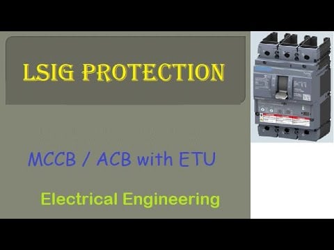
Watch LSIG Protection in Circuit Breaker by Smart Educare for a visual explanation. Model-specific SUTON documentation and the approved panel study remain controlling.