


RCCB for VFD selection must account for the drive input filter, switching waveform, motor-cable length, leakage current, EMC components and the residual-current type recognized by the device. A standard sinusoidal assumption can be inadequate for an inverter-fed motor. Start with the drive and RCCB manuals, the earthing arrangement and the required protection objective. Measure normal leakage in the real operating modes and verify that sensitivity, waveform response, time delay and selectivity remain within the project study.
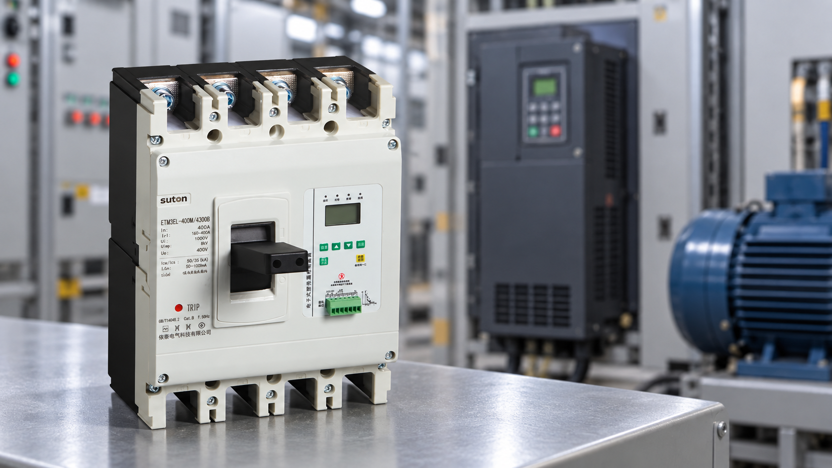
Start with the drive manual and filter data
Identify the drive topology, input filter, bypass contactor, motor cable length, shield termination, carrier frequency and any built-in residual-current monitoring. Filters can add normal leakage, while common-mode currents and cable capacitance can change during acceleration or at different speeds. Ask the drive supplier which residual-current device types and test methods are compatible; do not infer them from the motor nameplate.
Measure each operating mode
Record leakage with the drive stopped, starting, running at representative speeds, braking and in bypass if present. Review the total leakage of multiple drives at the feeder. Check upstream/downstream selectivity and required disconnection time before adding a delay. A higher threshold may reduce nuisance trips but can also defeat the protection objective.
Keep EMC and safety decisions together
Do not remove an EMC filter or disconnect a protective conductor as an informal fix. Review the complete installation, shield bonding, cable route, enclosure and earthing arrangement with the drive and RCCB manufacturers. Keep the measured result, model codes and study revision in the commissioning pack.
Build a circuit-specific decision
| VFD input | Why it affects RCCB | Evidence to request |
|---|---|---|
| EMC filter | Adds normal leakage to earth | Filter type, leakage data and installation mode |
| Motor cable | Capacitance and length affect common-mode current | Cable length, shield termination and measured leakage |
| Drive waveform | Residual current may not be purely sinusoidal | Compatible RCCB type and manufacturer instructions |
| Multiple drives | Leakage can accumulate upstream | Per-drive and total leakage study |
The table is a screening aid, not a substitute for the exact product manual or protection study. Confirm the assumptions with the engineer responsible for the installation and keep the evidence revision with the purchase record.
Read the manufacturer evidence
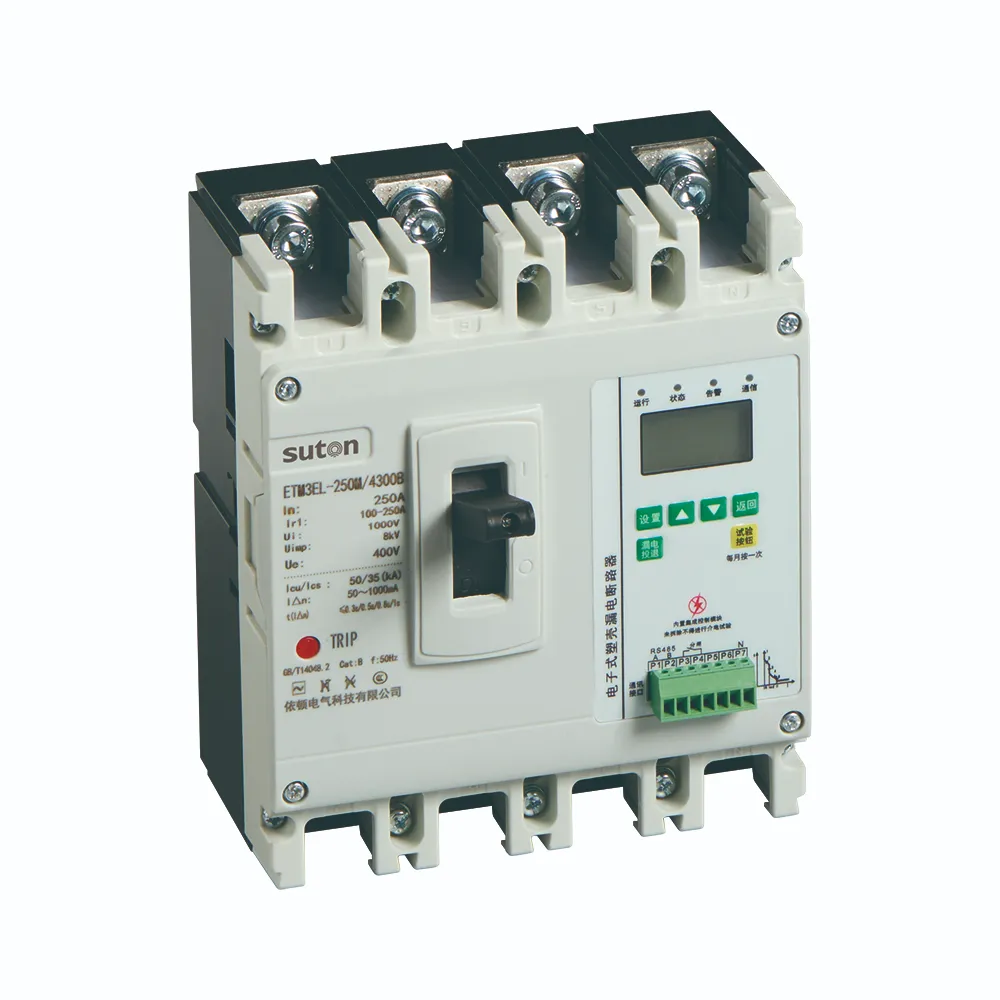
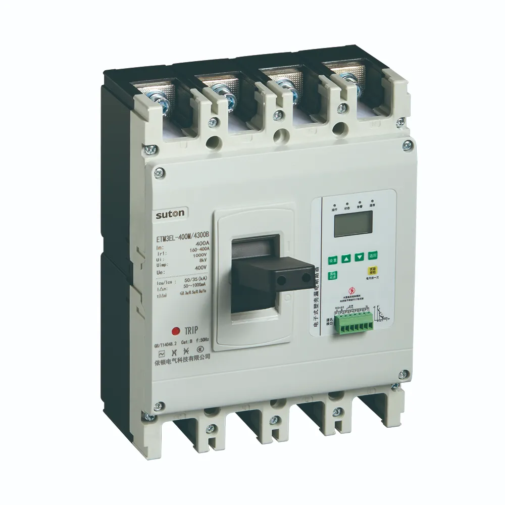
Ask for the operating characteristics, no-trip and trip limits, residual-current waveform response, time delay, pole arrangement, terminal diagram, test method and coordination information for the exact catalog code. If an accessory or electronic module changes the sensing path, treat it as a new technical review. A nominal mA value or current rating alone cannot prove compatibility.
Compare the offered code with the approved schedule. Check the line/load direction, neutral terminal, protective-earth arrangement, enclosure, ambient conditions and tightening instructions. Record any limitation instead of marking an unverified item compliant. The circuit-breaker types guide provides the parent overview, while rccb sensitivity 30ma 100ma 300ma and rccb selectivity coordination cover adjacent RCCB decisions.
Commission, document and recheck
Before energization, confirm device identity, settings, conductor placement, labels, barriers, test-button operation and isolation boundaries. Record measured leakage or test values, instrument details, date, operating mode and the as-left drawing revision. A test button exercises a defined internal path; it does not prove every conductor is de-energized or that a fault study is correct.
After a source, load, cable, firmware, filter, setting or accessory change, repeat the relevant review. Keep normal, standby, transfer, generator, bypass and maintenance modes visible in the documentation. If the evidence does not cover the proposed combination, mark it conditional and obtain engineering approval before shipment or commissioning.
Separate the protection objective from the symptom
An RCCB is one part of a protection system. It detects residual current according to its design, while overcurrent protection, earthing, bonding, conductor sizing, disconnection time and equipment instructions address other hazards. A suitable selection starts by stating what the device must achieve and which operating modes are included. “It trips” or “it does not trip” is not, by itself, enough information to change the device.
Keep the single-line diagram, source arrangement, neutral bonds, load list, cable routes, calculated fault levels and commissioning records together. The same enclosure may contain circuits with very different leakage waveforms and maintenance boundaries. A family brochure can explain a product range, but the exact catalog code, pole arrangement, sensitivity, delay, waveform type, terminals and accessories govern the installed result.
Check the actual circuit before changing settings
Identify every conductor passing through the residual-current sensor, every neutral connection, every protective-earth path and every parallel return. Mark normal, standby, transfer, generator, bypass and maintenance modes. In a multi-source system an apparently minor neutral bond can change the measured residual current. In a power-electronic load, filters and switching devices can add normal leakage or non-sinusoidal components.
Measure or calculate normal leakage with the expected loads operating and record the instrument, circuit state and result. Do not disconnect protective conductors, defeat an interlock or create a test fault as a shortcut. Testing must follow the approved method and be performed by competent people under the adopted rules. If the result is outside the design margin, investigate the cause before increasing a threshold or adding delay.
Use a documented procurement and verification loop
In an RFQ, state the system voltage and frequency, phase and neutral arrangement, rated current, earthing system, maximum and minimum fault current, residual-current objective, required sensitivity and delay, breaking capacity, waveform type, pole count, accessories, mounting, ambient conditions and required evidence. Ask the supplier to decode the complete model number and identify which options are included in the quotation.
Before approval, compare the offered code against the study and installation drawing. Confirm line/load markings, terminal torque, test circuit, neutral treatment, trip indication, auxiliary contacts, shunt trip, remote operation and enclosure clearances. At handover retain the approved datasheet revision, wiring diagram, settings, test result and as-left single-line diagram. Repeat the review after a load, source, cable, setting or accessory changes.
Safety and evidence boundary
HSE electrical-safety guidance emphasizes competent work and safe isolation. IEC 60947-2:2024 provides product-standard context for low-voltage circuit breakers; apply the edition and local rules adopted by the project. These references do not approve a particular SUTON combination. The responsible engineer must confirm the installation study, protective measures and acceptance test.
Use the SUTON residual-current MCCB product page as a starting point for a quotation. Request the exact technical documents for the proposed model rather than inferring capability from a photograph or a neighboring product.
Questions to close before release
Ask the supplier to identify the exact sensing conductors, residual-current type, rated residual operating current, non-operating behavior, delay range, pole mechanism, neutral treatment, test circuit and compatible accessories. Ask which assumptions are based on a tested combination and which require a project calculation. Put the answers beside the requirement in the compliance schedule, then keep the schedule with the purchase order, drawing and commissioning plan.
When a fault or unexpected trip is reported, preserve the as-found state where safe, record the operating mode and avoid changing several variables at once. A controlled one-change-at-a-time investigation makes the result traceable. If the equipment must be returned to service, document the temporary condition and the responsible approval. A replacement with a different sensitivity, waveform type, pole arrangement or accessory is a new selection review, even when its enclosure looks similar.
Finally, label the affected circuit and retain photographs of the as-found wiring when permitted by the site procedure. Clear evidence reduces repeat visits and helps the next technician understand why a setting or device was selected.
Include a short acceptance checklist: identity, terminals, conductor routing, settings, test result, drawing revision and approval. This simple record is valuable for procurement, commissioning, maintenance and later fault finding.
Do not close the issue until the approved drawing and the installed conductors agree. Record final signoff, date and responsible reviewer.
Keep the operating limits visible on the panel documentation for maintenance staff and future inspections at the site.
Include the approved source diagram, device code and test evidence in the handover file so future changes can be reviewed against the same protection assumptions.
Educational video
This neutral educational lesson provides context for residual-current protection. It does not replace the project calculation, manufacturer instructions or safe-work procedure.
Watch Electrical Safety Course #6 – Residual Current Devices and PPE on YouTube.
Frequently asked questions
Why can a VFD cause RCCB trips?
EMC filters, switching behavior, motor-cable capacitance and common-mode currents can increase or change residual current. Investigate the installation rather than masking it with a higher threshold.
Can any RCCB type be used with a VFD?
No. The required residual-current type and response depend on the drive, supply, filters and manufacturer instructions.
Does adding a delay solve VFD leakage?
Delay can change coordination but does not remove leakage or prove disconnection compliance. Check the complete protection study.