


MCCB accessories selection should start with the control function and failure response, then map that function to the exact breaker, trip unit, control voltage and wiring. A shunt trip, undervoltage release, motor operator, auxiliary contact and alarm contact do different jobs. A status contact reports mechanism position; it does not prove that conductors are de-energized. Confirm the complete product code, accessory compatibility, terminal arrangement, control-circuit protection, interlocking and commissioning tests before ordering. The final choice belongs in the approved control schematic and purchase schedule.
Define the required signal or action
Write a duty statement for each accessory. “Open the breaker on emergency stop” points toward a shunt trip or an approved trip relay. “Prevent closing when control power is absent” may require an undervoltage release. “Tell the PLC that the breaker is open” requires an auxiliary contact, while “tell the PLC that an overload or fault caused the trip” may require an alarm contact. These signals should not be combined into one vague request for remote control.
| Accessory function | What it does | Checks before approval |
|---|---|---|
| Shunt trip | Opens the mechanism when its control input is energized | Control voltage, pulse/continuous duty, reset behavior and fail-safe philosophy |
| Undervoltage release | Prevents or releases closing when its control voltage is absent or low | Pickup/dropout values, restart sequence and emergency-stop logic |
| Motor operator | Charges or operates the mechanism for remote opening/closing | Motor voltage, cycle duty, interlocks and manual override |
| Auxiliary contact | Reports mechanism or contact position as defined by the maker | Contact rating, changeover logic and terminal numbers |
| Alarm contact | Reports a trip or fault condition as defined by the product | Trip cause, reset behavior and PLC interpretation |
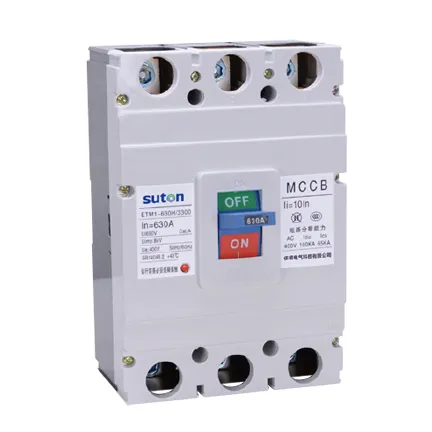
The exact meaning of a contact depends on the manufacturer wiring diagram and the installed option package.
Match the accessory to the exact MCCB code
Accessory compatibility is not guaranteed across a product family. Frame size, pole count, trip technology, fixed or plug-in mounting, left or right position and production revision can change the available option. Decode the offered breaker code and ask for the accessory table and wiring diagram for that code. A photograph of a similar breaker is not evidence that its terminal kit or release is compatible.
IEC 60947-2:2024 defines the circuit-breaker product scope, but the control functions and accessory combinations remain model-specific. Use the edition and national adoption specified by the project. Ask the supplier to identify whether an accessory is factory-fitted, field-installable or unavailable after shipment.
Design the control circuit and failure response
State what should happen when control power is lost, a wire breaks, a PLC output fails or a contact welds. An undervoltage release can support a de-energize-to-trip philosophy, while a shunt trip can support an energized trip command. Neither is automatically the right emergency function. Add fuses or miniature protection to the control circuit as required, identify the source, and keep control voltage separate from the power circuit in the drawings.
For motor operators, define electrical and mechanical interlocks so a remote close cannot occur while the breaker is withdrawn, locked out, under maintenance or exposed to an unsafe source condition. For status contacts, define whether the PLC needs “open,” “closed,” “trip,” “ready” or “spring charged.” Do not use one auxiliary contact for several meanings without a documented logic diagram.
Verify installation, testing and handover
Check terminal numbers, contact ratings, conductor size, ferrules, separation, control-voltage polarity where applicable, and access for testing. Test each command and feedback point with the power circuit in a safe approved state. Simulate loss of control voltage, shunt-trip operation, manual operation and an alarm condition. Record the as-left state and labels.
The UK Health and Safety Executive electrical-safety guidance reinforces the need for safe isolation and competent work. It is not a substitute for the local project rules, but it is a useful reminder that remote control does not remove the need to isolate and verify. The fixed, plug-in and drawout MCCB guide covers mounting interfaces, while the neutral-protection guide covers a related protection option.
RFQ checklist
- Identify the exact MCCB, frame, poles, trip unit and mounting.
- Describe every required remote action and feedback signal.
- State control voltage, source, duty cycle and failure response.
- List shunt, undervoltage, motor, auxiliary and alarm accessories separately.
- Request the accessory compatibility table and wiring diagram.
- Define interlocks, labels, tests, certificates and handover records.
- Require the supplier to decode the complete option code.
Start with the SUTON ETM1 MCCB page, then request the model-specific accessory schedule before purchase approval. The circuit-breaker types guide is the parent overview and the maintenance checklist covers handover checks.
Build an approval record that can be audited
Record the exact catalog code, frame, rated current, poles, voltage, breaking capacity, trip-unit type, settings, terminals, accessories, mounting arrangement and document revision. Keep the as-designed, as-installed and as-left information separate. A family brochure is not enough when several ratings or configurations share an enclosure.
The technical file should include the single-line diagram, fault-current study, protection study, conductor schedule, panel drawing, manufacturer instructions and commissioning results. If a value comes from a calculation, state the source inputs and revision. If it comes from a manufacturer table, identify the exact device combination.
Commissioning and safe-work boundary
Before energization, verify device identity, settings, pole arrangement, conductor placement, terminal preparation, tightening method, barriers, labels, handle operation, auxiliary functions and mechanical interlocks. Testing and fault studies must be carried out or approved by qualified people under the adopted rules. This article supports specification work and does not authorize energized work.
After a serious fault or unexplained trip, do not simply reset the breaker. Investigate the cause, inspect the breaker and connected equipment as required by the manufacturer, and confirm that settings remain correct. Record any replacement, conductor work or setting change.
Information to include in an RFQ
Give bidders the system voltage and frequency, AC or DC duty, poles and neutral arrangement, normal current, calculated maximum and minimum fault current, required breaking capacity under the named standard, trip functions and settings, utilization duty, conductor and terminal details, accessories, control voltage, mounting, ambient conditions and required documents. Ask for a completed compliance schedule rather than an unqualified family datasheet.
Require the offered model to be decoded in full. Options such as electronic trip units, earth-fault functions, shunt trips, undervoltage releases, auxiliary contacts and motor operators can change the product code and wiring. An accessory shown in a brochure photograph is not automatically part of the quotation.
Close the evidence loop before purchase approval
Place each supplier answer beside the project requirement and classify it as compliant, conditional or noncompliant. Do not treat a blank cell as compliance. Resolve alternative offers with the same technical review applied to the base offer, and retain the approved schedule with the purchase order. Confirm that the datasheet revision, drawing, setting sheet and installation instructions all describe the same catalog code and option package.
Ask who owns the fault-current calculation, who sets the protection, and which operating modes were included. Record assumptions that still depend on vendor data. This small discipline prevents a late discovery about neutral sensing, a mounting base, an ambient limit or an accessory from becoming a panel change after shipment.
At handover, keep the final model code, setting record, test results and marked-up single-line diagram together. Future maintenance staff should be able to see exactly which neutral function was approved and which conductors or sources were included in that decision.
Where the quotation offers alternatives, ask the supplier to identify every changed interface and every changed assumption. A different pole arrangement, connection kit or thermal limit can alter the panel drawing, coordination study and commissioning plan even when the front label appears similar.
Keep those clarifications with the approved purchase record so a later replacement is checked against the same interface and duty.
Include the final arrangement in the maintenance handover package for future maintenance and detailed technical review.
Keep the final record with the equipment
At handover, retain the model code, settings, test results, marked-up drawing, accessory list and maintenance findings together. Future technicians should be able to see which function was approved, which test method was used and which assumptions applied to the installed device.
Where a quotation offers alternatives, identify every changed interface and every changed assumption before approval. A different accessory, terminal kit or test adapter can alter the panel drawing, coordination study and commissioning plan even when the front label appears similar.
Do not close a maintenance or test record with a generic pass statement. State the actual device, measurement, limitation, corrective action, follow-up date, evidence and person who authorized return to service.
Keep the signed record with the equipment history and make unresolved actions visible to the next responsible engineer.
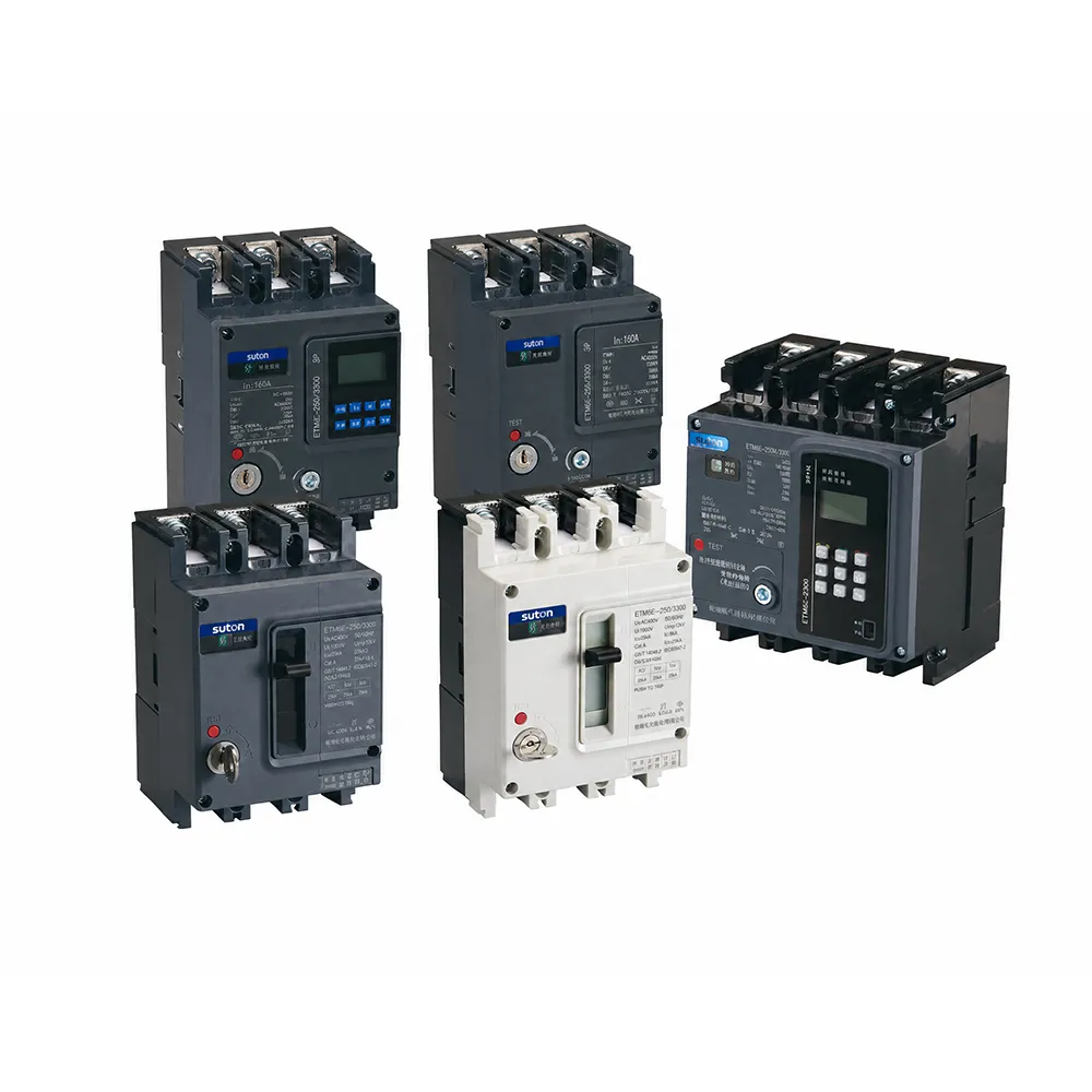

Related SUTON technical resources
Use the linked product and related guides as procurement starting points, then verify the offered device against the project study. Similar-looking MCCBs can have different ratings, terminals, trip functions and approvals.
Educational video
The following neutral educational video supports the electrical principle discussed here. It does not replace project calculations or manufacturer instructions.
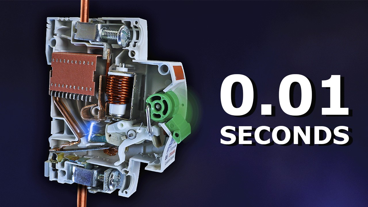
Watch Why Circuit Breakers Do Not Protect People on YouTube.
Frequently asked questions
Does an auxiliary contact prove that a circuit is safe to touch?
No. It reports a defined mechanism or contact state. Safe isolation still requires the approved isolation and verification procedure.
Is a shunt trip the same as an undervoltage release?
No. A shunt trip normally opens on an energized command, while an undervoltage release responds to loss or low control voltage according to its specification.
Can an accessory be selected from a product photograph?
No. Use the exact model code, accessory table and wiring diagram.