


For panel builders, afci breaker installation is a controlled sequence—isolate power, land the branch hot and load neutral on the AFCI device, connect the pigtail or modular neutral per the manual, energize, trip the test function, and record acceptance—not a shortcut for swapping GFCI labels. The sections below lock install scope, wiring order, DIN-rail AFDD limits, test-button checks, and a panel-builder checklist, with links to comparison and protection guides when function labels still need clarification.
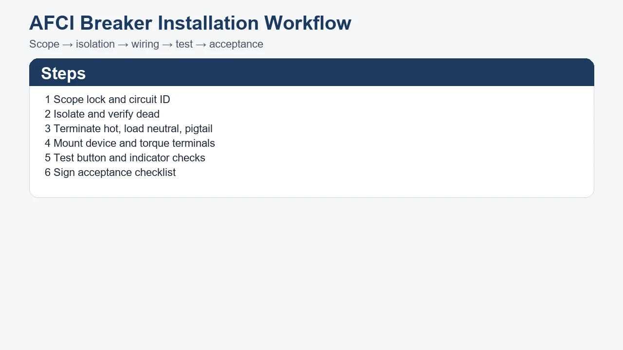
Define AFCI Breaker Installation Scope Before Opening the Panel
Confirm the circuit needs arc-fault protection on an AFCI-class device before you open the cover, because install steps assume the function label is already correct.
An AFCI breaker installation job starts with the protective function, not the amp rating. The branch may need arc-fault interruption for dangerous arcing signatures, but that is not the same purchase line as personnel ground-fault protection. If the drawing still says “GFCI” for a wet-location shock duty, stop and read the AFCI vs GFCI guide before you land conductors on the wrong device family. When the project is still at protection-layout stage, the AFCI protection guide owns strategy; this article owns execution after the function is fixed.
Record three scope fields on the job sheet: circuit ID, form factor (load-center plug-in breaker versus modular DIN-rail AFDD), and whether the work is new branch wiring or a breaker swap on an existing circuit. Sub-panel work may need upstream feeder isolation beyond the local main handle, so note which panel actually removes power from the bus you will touch.
| Install path | Typical market / enclosure | Sections in this guide |
|---|---|---|
| US load-center plug-in AFCI | NEC-style residential/commercial branch panels | Steps 1–3, 5–6 (scope, isolation, wiring, test, checklist) |
| IEC modular DIN-rail AFDD | ETB9LAF-class modules on DIN35 rail | Step 4 plus shared Steps 1–2, 5–6 |
Step 1 — Define scope before opening the panel. Confirm the arc-fault function label, form factor, and circuit ID on the job sheet first.
| Scope field | What to verify | Why it blocks rework |
|---|---|---|
| Protective function | AFCI / arc-fault duty required on this circuit ID | Prevents GFCI mis-install |
| Form factor | Load-center breaker vs DIN-rail AFDD | Different mount and torque rules |
| Isolation point | Main vs upstream feeder for sub-panels | Live bus risk |
| Circuit identity | Panel name, breaker number, pole count | Traceability on checklist |
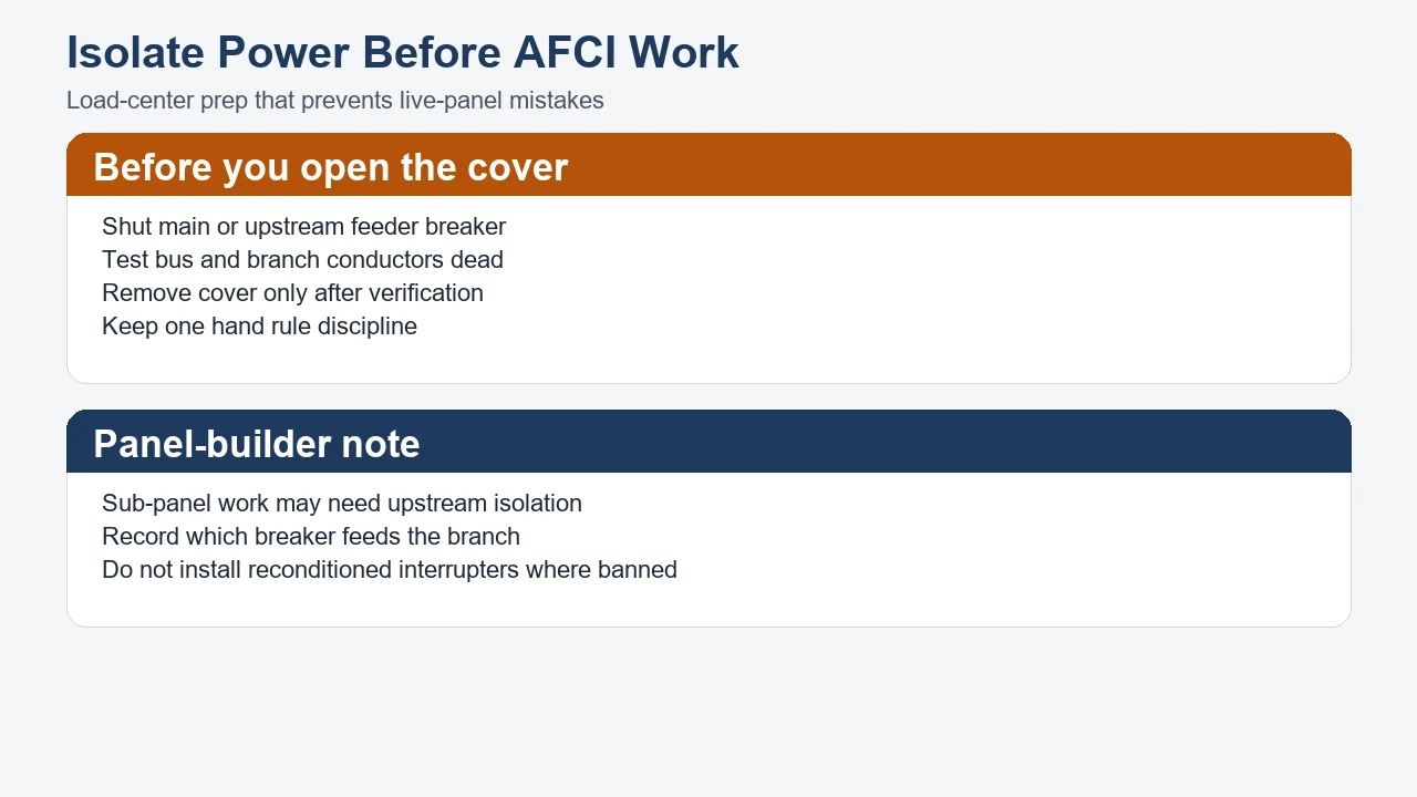
Isolate Power and Verify the Panel Is Safe to Work
Step 2 — De-energize and verify dead. Isolate upstream power before opening the panel or DIN-rail assembly door.
Isolate upstream power before opening the panel or DIN-rail assembly door. On a service panel, move the main breaker to OFF. On a sub-panel fed from another distribution board, the feeder breaker in the upstream panel may be the real isolation point—turning off the sub-panel main is not always enough if you must work on the feeder lugs. After lockout, test from hot to neutral and hot to ground at the branch you will touch; absence of voltage is the working assumption, not the label on the breaker handle.
Label the circuit under work on the cover or a temporary tag so another crew does not re-energize while conductors are exposed. Keep cover screws organized and replace the cover before restoration unless manufacturer instructions require an exposed-bus test. Trade install guides agree that the test function must be exercised after energization and that used or reconditioned interrupters are a poor specification habit on new work.
Terminate Hot, Load Neutral, and AFCI Pigtail Wires Correctly
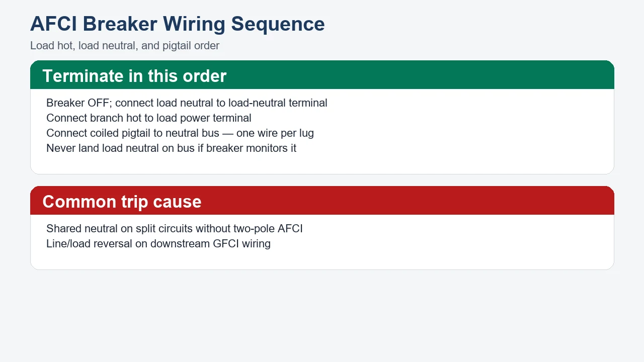
Step 3 — Land load neutral, hot, and pigtail. Route branch conductors to the AFCI terminals with the handle OFF.
Land branch neutral on the AFCI load neutral terminal so the device can monitor current on the protected circuit. Move the existing neutral from the neutral bus to the AFCI load-neutral terminal (often marked with a white dot or “Load Neutral”). Connect the branch hot to the load power terminal. Attach the factory coiled pigtail to the neutral bus using an open lug—one wire per terminal, fully seated and torqued per the breaker manufacturer’s instruction sheet for the SKU you are installing.
| Terminal / conductor | Typical label | Connection rule |
|---|---|---|
| Branch neutral (white) | Load Neutral / white dot | On AFCI breaker, not the bus |
| Branch hot (black) | Load Power / black | On AFCI breaker |
| Coiled pigtail (white) | Panel neutral / pigtail | To neutral bus—one wire per lug |
| Ground (green/bare) | Ground bus | Per panel bonding layout |
Work with the AFCI handle in the OFF position until terminations are complete and the cover is ready. A multimeter check for dead shorts on the branch before energization is cheap insurance against a mis-stripped conductor or crossed hot/neutral in the box.
Important: A single-pole AFCI on one hot of a three-wire cable with a shared neutral can trip immediately or refuse to hold ON; Fine Homebuilding’s AFCI breaker guide notes that both hots on such a cable may need a two-pole AFCI when arc protection is required on the shared-neutral arrangement. Match pole count and neutral routing to the cable, not only the amp rating.
Do not use AFCI wiring steps as proof that a GFCI duty is satisfied. Personnel ground-fault protection still needs its own function and terminals when the specification names that hazard.
Mount and Wire DIN-Rail AFDD Devices to Published Limits
Step 4 — Mount modular AFDD hardware to published limits. Use DIN35 mount, published torque, and wire range for ETB9LAF-class devices.
Modular DIN-rail AFDD installation follows the device manual and the live parameter table, not load-center pigtail habits. The published ETB9LAF-63 Series Arc Fault Detection Device page lists DIN35 installation, wiring torque 3 Nm, and wire capacity 1.0–16 mm². Clip the device on the rail per the appearance and installation drawing on that page, route conductors into the wiring ports without forcing oversize cable into a terminal that will not accept it, and torque to the published value with a calibrated tool—not finger tight.
After an arc-fault or leakage trip, the ETB9LAF indicator behavior published on the product page requires pressing the indicator button before reclosing; arc trips flash red for about ten seconds before steady red, while leakage trips use the green indicator channel on the same family description. Treat those patterns as commissioning notes: record which indicator sequence you observed when you exercise the device during acceptance.
DIN-rail AFDD installation does not automatically satisfy a US load-center AFCI breaker specification on the same drawing line. Match the catalog family to the form factor the buyer named, and keep UL 489 / UL 1699 education frameworks in the standards conversation without inventing a SUTON listing that the page does not publish.
Run AFCI Test-Button and Indicator Checks After Energization
Step 5 — Exercise the AFCI test button after energization. Press the test button and confirm a trip before handoff.
Post-install AFCI verification is not optional decoration. With loads downstream unplugged or switched off where practical, energize the panel, move the new AFCI handle to ON, and press the test button on the breaker face or the test feature described in the modular manual. The device should trip open; reset only after you confirm wiring and indicator rules. If the handle cannot stay ON after correct terminations, recheck load neutral placement, pigtail seating, and shared-neutral pole count before blaming “nuisance tripping.”
Retail and trade how-to sources agree: a test button that fails to trip means defective hardware or a wiring error—either way the circuit is not ready for handoff. Repeat the test after any rework to the same terminals.
For ETB9LAF-class devices, combine the test-button or manual test procedure with the published indicator reset step so the next operator knows whether the last event was arc or leakage class.
Close the Job with an Installation Acceptance Checklist
Step 6 — Record acceptance fields and sign off. Capture circuit ID, torque, wire size, and test-button result on the job sheet.
A panel-builder acceptance row should let a third party verify the install without opening every connection again. Where adopted code education prohibits reconditioned AFCIs and GFCIs, record new-stock devices only; even outside that jurisdiction, anonymous used interrupters are a poor specification habit.
| Acceptance field | Record | Pass criterion |
|---|---|---|
| Circuit ID | Panel + breaker number | Matches drawing |
| Device marking | Catalog / label photo or SKU | Matches RFQ function |
| Wire size | mm² or AWG landed | Within device table |
| Torque | Tool reading (e.g. 3 Nm on ETB9LAF) | Within published limit |
| Test button | Trip / reset noted | Trips on test |
| Installer | Name, date, company | Signature or ticket ID |
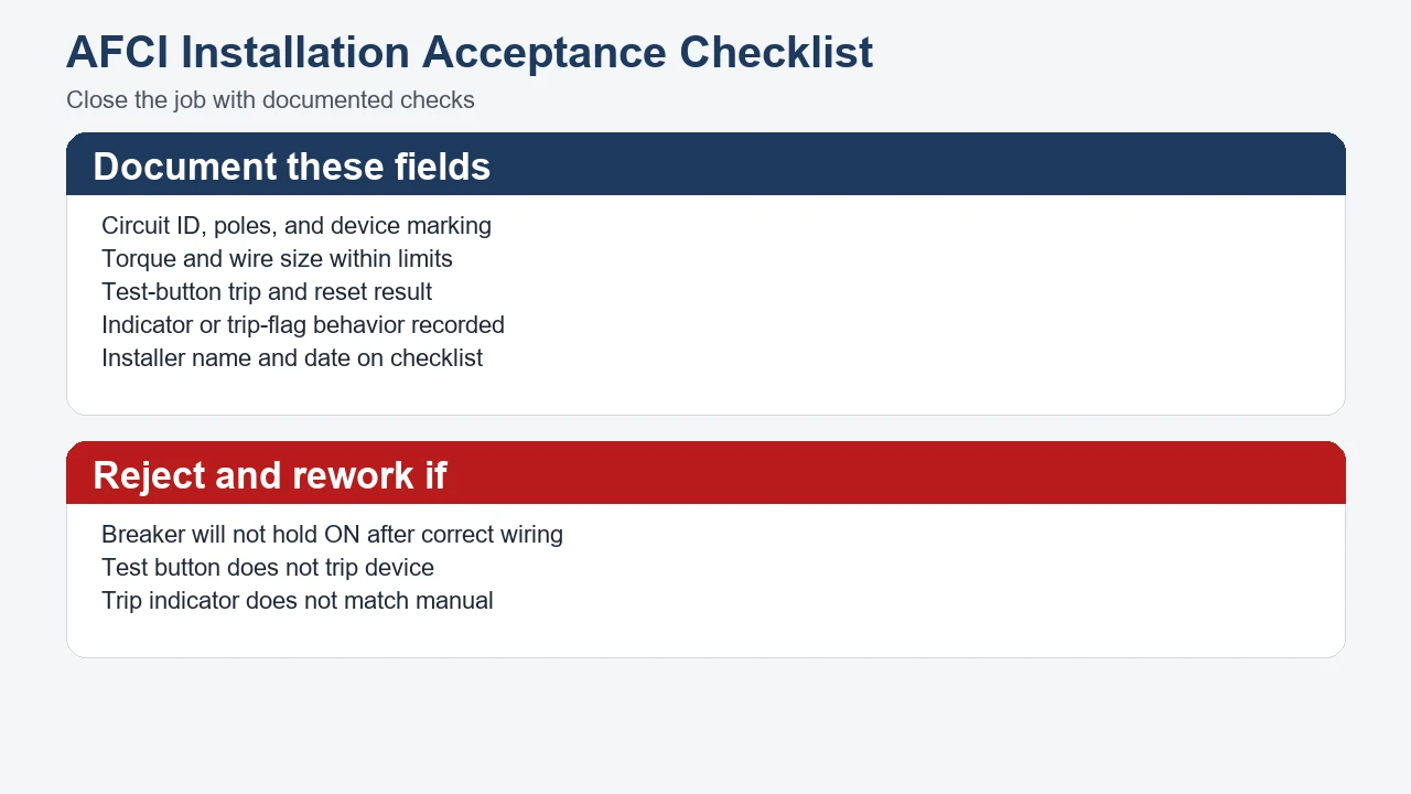
Attach the checklist to the panel schedule or digital maintenance record. If the job is modular, add a photo of the DIN-rail row showing the AFDD position so future service can find the device without tracing every module.
Route ETB9LAF AFDD Product Inquiries Through Modular DIN-Rail Paths
Use SUTON’s modular DIN-rail hub and the published ETB9LAF AFDD page for modular install documentation—without inventing a dual-function UL AFCI/GFCI SKU the catalog does not list.
The modular DIN rail products category is the upward path for AFDD, RCBO, and related modular families. For arc-fault detection hardware that matches DIN-rail form, the ETB9LAF-63 Series Arc Fault Detection Device page is the first-party route for mount, torque, wire range, and indicator behavior. Those links are inquiry anchors, not certificate transfers—confirm markings and instructions against the project package before purchase.
When the install scope is settled and documentation is ready, contact SUTON with circuit ID, form factor, torque confirmation, and test results from the checklist above. Keep AFCI install notes beside the circuit ID so purchasing cannot swap a combination-type label for a ground-fault duty the job never required.
FAQ
How do you install an AFCI breaker?
Isolate power, land load neutral and hot on the AFCI terminals, connect the pigtail to the neutral bus, reinstall the cover, energize, and press the test button to confirm a trip. Modular DIN-rail AFDD jobs add DIN35 mount and published torque limits.
Where does the neutral wire go on an AFCI breaker?
The branch neutral goes to the AFCI load-neutral terminal. The coiled white pigtail from the breaker goes to the panel neutral bus on its own lug.
Do you need to test an AFCI breaker after installation?
Yes. Press the test button after energization; the device should trip. Repeat after any wiring rework.
Why won’t an AFCI breaker stay on?
Check load neutral placement, pigtail connection, and whether a shared-neutral three-wire cable needs a two-pole AFCI instead of a single-pole device on one hot.
Can you install an AFCI breaker in a subpanel?
Yes, when upstream isolation removes power from the bus you will touch. The feeder breaker in the upstream panel may be the required isolation point.
What torque applies to ETB9LAF DIN-rail terminals?
The published ETB9LAF product page lists wiring torque 3 Nm. Use that value with a calibrated tool unless a superseding document on the same product page replaces it.
Does AFCI breaker installation replace GFCI work?
No. AFCI installation completes arc-fault protection wiring; GFCI or residual-current duties need their own function and hardware. Use the AFCI vs GFCI guide when labels are mixed on the drawing.