


An electrical control panel should be planned from the process outward: establish how the machine operates, assign protection to each circuit boundary, and only then release the component BOM. That order connects the operating story, fault and load data, control functions, enclosure conditions, and applicable standards to parts that a builder can assemble and a supplier can quote consistently.
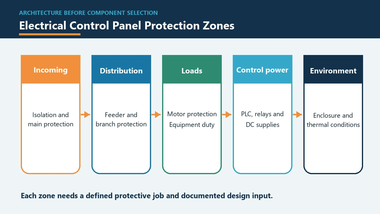
A cabinet-and-breaker list can look complete while still missing the information that determines whether those devices fit the job. The sections below move from system boundary to project inputs, protective roles, BOM control, physical constraints, and component-specific supplier questions.
Define the Electrical Control Panel Boundary Before Choosing Parts
Start by identifying what the assembly controls and where its supply, control, and field interfaces begin and end. An industrial control panel coordinates an enclosure, incoming power, protected distribution, control power, switching, PLC and I/O functions, operator interfaces, terminals, wiring, and environmental provisions required by the application.
A circuit breaker is one protective device within that wider system. The panel also has functional relationships that a breaker cannot establish by itself, such as how a safety input changes machine operation, which output drives a contactor, or which terminal connects a field sensor.
Machine electrical equipment may bring a machine-specific control and safety path into the project, while a low-voltage assembly has its own construction and performance evidence. Classifying that boundary early keeps the BOM and handover documents aligned with the actual application.
The project name alone does not settle the boundary. A populated distribution assembly is better handled through a panel board planning path, while a multi-motor bucket architecture belongs in a motor control center plan.
Consider a buyer who receives an enclosure size, a breaker list, and a PLC brand but no functional narrative. The missing boundary makes it impossible to tell whether the list covers machine control, general distribution, motor feeders, or a mixture with different engineering and documentation responsibilities.
Start with the Operating Story and Project Inputs
The sequence of operations, safety functions, supply and load data, fault information, I/O, communications, and environment should lead the parts list. A sequence of operations is the functional narrative for normal states, transitions, faults, resets, permissives, and safety responses—in plain language, the operating story for what the machine should do and how it should react.
A panel builder asked to price parts before receiving that story can only guess at contactor duties, PLC I/O, control-power demand, alarms, and protected branches. Procurement can prevent that guesswork by requiring a compact input pack before accepting a BOM release.
| Project input | What it establishes | Downstream record it should influence |
|---|---|---|
| Supply and earthing data | Incoming interface and protective-conductor context | Single-line diagram, incomer role, terminal schedule |
| Load and motor schedule | Operating duty, starting behavior, branch functions | Feeder schedule, switching and overload roles |
| Available fault current | Severity of a short circuit at the connection point | Interrupting-duty and SCCR decisions |
| Sequence, faults, and safety responses | Required states, interlocks, resets, and stops | Control narrative, schematics, I/O list |
| I/O and communications list | Field devices, signal types, logic and interfaces | PLC layout, control power, terminal and cable records |
| Environment and service conditions | Exposure, access, mounting, and heat-removal needs | Enclosure, spacing, cooling, and maintenance plan |
| Governing rules and customer specifications | Equipment path and required evidence | Design basis, inspection, test, and handover documents |
A single-line diagram, also called a one-line diagram or SLD, then gives the high-level map of how power enters and divides into major branches. It should agree with the load schedule and operating story; otherwise the drawings and BOM describe different systems.
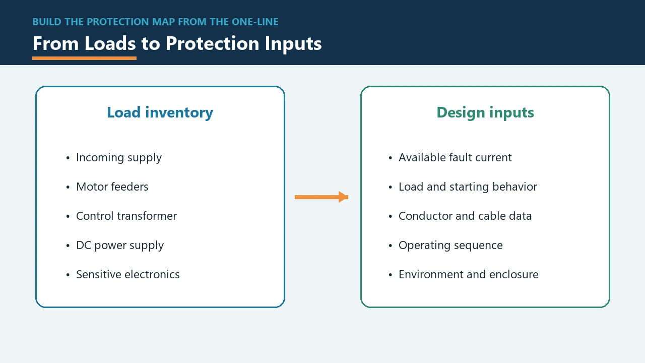
Build Protection Around Circuit Roles, Not a Flat Parts List
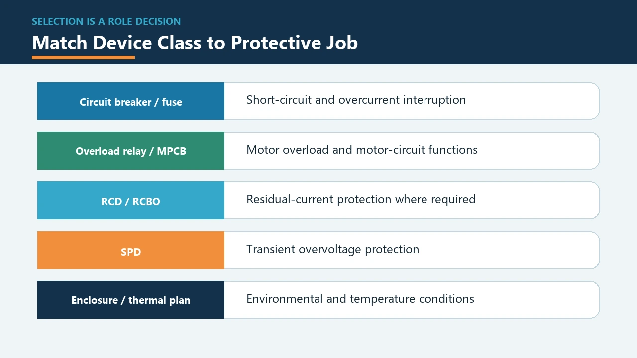
Assign protection by the circuit or equipment boundary it serves before choosing a device class or model. Incoming isolation and overcurrent, branch short-circuit protection, motor overload, control-power protection, surge or residual-current functions, and assembly short-circuit performance answer different questions.
Disconnecting means establish the required isolation function, while branch-circuit protection and motor overload protection address different downstream duties. The exact combination follows the circuit roles established by the operating and load information.
Available fault current is the prospective current at a circuit location during a short circuit—the severity of the fault the system may have to handle there. Interrupting rating describes a protective device’s ability to interrupt that fault at the applicable voltage and conditions, while short-circuit current rating describes the stated fault-duty capability of a component or assembly under its defined conditions.
| Protected boundary | Protective job | Evidence needed before selection | Record carried forward |
|---|---|---|---|
| Supply and incomer | Isolation and incoming fault/overcurrent duty | Supply voltage, available fault current, earthing and operating needs | SLD role, device data, accessories |
| Branch or feeder | Conductor and downstream circuit protection | Load duty, conductor data, circuit voltage and fault level | Feeder schedule and schematic reference |
| Motor circuit | Short-circuit and sustained-overload functions | Motor/load schedule, starting and operating duty | Motor feeder and overload records |
| Control-power input and distribution | Protection for the supply input, conductors, and control branches | Power-supply instructions, inrush, conductors and connected duty | Control schematic and terminal schedule |
| Surge or residual-current function | Transient or leakage-related protection when required | System arrangement, governing rules and device instructions | SLD, coordination notes and product data |
| Finished assembly | Short-circuit performance of the combined construction | Component data, circuit arrangement and applicable assembly path | Assembly design and verification file |
A main circuit breaker therefore does not close every protection decision. One incoming device on the drawing leaves open the duties of downstream feeders, motor overload relays, control branches, surge protective devices, residual-current protection, and the completed low-voltage assembly.
Important: In U.S. workplace scope, OSHA 1910.303 connects nominal circuit voltage and available current with interrupting rating, circuit impedance, protective-device coordination, and component SCCR. These same data points belong in the project decision set even when another jurisdiction supplies the governing rule.
Two supplier quotations may show the same current label yet answer different fault duties because the RFQ omitted circuit voltage and prospective fault current. That comparison is incomplete until the ratings, conditions, and circuit role are visible together.
For a fuller distinction among MCB, MCCB, ACB, and related device classes, use the circuit breaker types guide after the protected role is clear.
Give Control-Power Protection Its Own Decision
Control power needs a separate boundary decision because its upstream input, power-conversion device, output conductors, and distributed branches do not share one automatic sizing rule. The selected protective device should have a stated job within that chain rather than a percentage remembered from another application.
An engineering-community question about sizing a breaker for a 24 VDC power supply captures the practical confusion: should the upstream device protect the supply, the branch wiring, or connected electronics, and how should input inrush be handled? The question is useful because it exposes the boundaries that a flat BOM hides.
Work through the control-power path in this order:
- Identify the incoming circuit and the conductors feeding the power supply or control transformer.
- Read the exact power-conversion device instructions for input protection, inrush, permitted upstream devices, and installation conditions.
- Record output conductors, distribution branches, loads, and any internal protection that affects the external design.
- Check how faults or loss of control power affect contactors, PLC outputs, alarms, resets, and safety functions.
- Carry the selected devices and their accessories into the control schematic, terminal schedule, and BOM.
A remembered ratio cannot replace those relationships. For example, capacitor charging at energization may affect the upstream device choice even though the steady control load is modest, while smaller output conductors may create a separate distribution decision.
Translate Functions into a Controlled Control Panel BOM
A controlled control panel BOM ties every line to a function, drawing, rating basis, interface, accessory, and substitution rule. This bill of materials is a procurement record linked to the electrical control panel design, not merely a spreadsheet of quantities and part numbers.
The difference becomes obvious when two parts appear interchangeable by frame size or current description. If one quote omits auxiliary contacts, terminal orientation, trip-unit details, or mounting hardware, the lower line price may represent a different build.
An approved alternate should preserve the functional role, ratings, interfaces, accessories, mounting needs, and required evidence recorded for the original line. Substitution then becomes a controlled engineering and procurement decision rather than a part-number shortcut.
| BOM or supplier field | Why it matters | Typical companion record |
|---|---|---|
| Item ID and drawing reference | Connects the part to its exact circuit and revision | SLD, schematic, layout |
| Functional role | States what the component must accomplish | Protection-role schedule |
| Rating and selection basis | Preserves the project data used for the choice | Load, fault and conductor data |
| Exact model and required options | Prevents a family name from hiding variant differences | Product data and order code |
| Accessories and interlocks | Captures auxiliary, operating, signaling, and mechanical needs | I/O list and control narrative |
| Termination and mounting interface | Protects wiring, space, and assembly compatibility | Terminal plan and panel layout |
| Evidence and document requirement | Makes required data available for review and handover | Datasheet, instructions, certificates where applicable |
| Approved-alternate rule | Defines which ratings, interfaces, and functions must remain unchanged | Substitution and revision record |
Control panel components beyond breakers also need this treatment: power supplies, transformers, contactors, overload relays, PLC hardware, terminals, wire duct, cooling equipment, labeling, and mounting parts can all affect the completed build. Accessories should be explicit BOM lines or clearly bound sub-items rather than assumptions in a supplier’s interpretation.
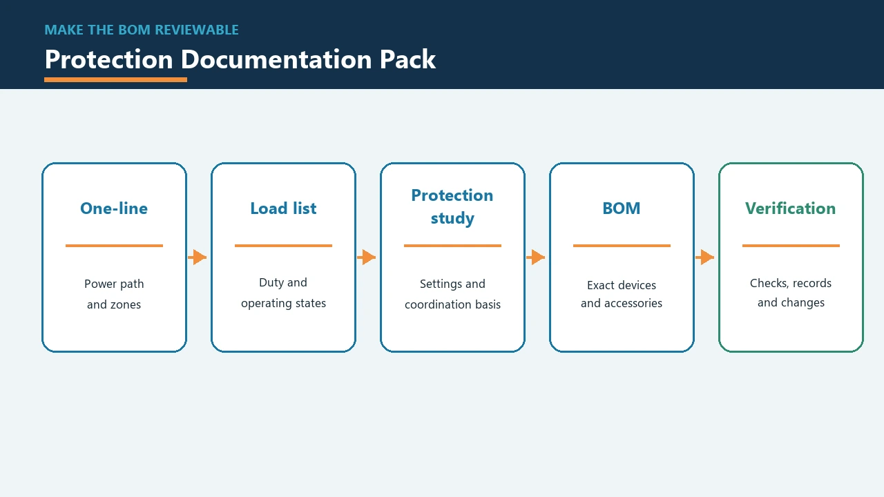
Resolve Enclosure, Layout, and Thermal Interfaces
Environmental, access, spacing, mounting, and cooling needs should be fixed before the enclosure and component layout are frozen. Enclosure and thermal management are part of the protection plan because they determine how equipment is exposed, supported, wired, cooled, inspected, and serviced.
A compact layout may reduce cabinet size while making wire bending, terminal access, heat removal, or later maintenance harder. Device instructions, site conditions, cable entry, door-mounted hardware, energized boundaries, and planned spare space should all reach the layout decision before procurement treats the enclosure as settled.
Thermal management begins with the losses and installation conditions of the chosen equipment, not with a decorative fan symbol. The design team should record ambient and internal conditions, ventilation or cooling method, obstruction risk, mounting clearances, and the effect of future additions.
Busbar electrical and mechanical duty is a separate design topic; the busbar system guide covers that handoff without turning this control-panel BOM into a busbar calculation.
Separate Product Standards from Assembly Verification
Product-standard evidence supports a component, while the applicable machine-equipment or assembly path governs the completed construction. Naming both layers prevents a breaker standard on one data sheet from being treated as proof for the whole panel.
IEC 61439-1 sets general definitions, service conditions, construction requirements, technical characteristics, and verification requirements for low-voltage switchgear and controlgear assemblies, used with the relevant part of the series. Where that path governs, the project should assign responsibility for the finished assembly evidence.
IEC 60204-1 covers electrical, electronic, and programmable electronic equipment of machines within its stated scope from the supply connection. Its public scope highlights overcurrent protection, short-circuit current rating, protective bonding, emergency stop, control-circuit protection, and documentation as connected machine-equipment topics.
IEC 60947-2 is a circuit-breaker product standard. It helps identify the product evidence expected for an applicable industrial breaker, but assembly construction, project fault duty, coordination, settings, and the final evidence file remain separate decisions.
For each project, record the governing jurisdiction and customer specification, applicable equipment and assembly route, design owner, assembly builder, inspection and test responsibilities, required drawings, and change-control process. That ownership should appear before the BOM is approved, not after a finished cabinet needs missing documents reconstructed.
Build the Supplier Package and Route Breaker Component Questions
A supplier package should carry the operating, circuit, fault, accessory, interface, and document inputs needed to answer one defined component role. Once that role is fixed, SUTON product families can be considered as component paths rather than as a complete control-panel offer.
For a conventional molded case circuit breaker candidate, compare the role schedule with the live ETM1 MCCB data and required accessories. ETM1 is presented for overload, short-circuit, and undervoltage protection functions, while project suitability still depends on the exact circuit and model choice.
If measurement and communication functions are approved requirements, the ETM3E intelligent measurement circuit breaker provides a model-specific inquiry path with an LCD, built-in communication, metering, and three-phase voltage and current display described on its product page. For a main or incomer role that calls for an air circuit breaker, the ETW3 intelligent air circuit breaker is a separate ACB component path.
Send the supplier the circuit role, voltage and load duty, available fault current, conductor and terminal interfaces, required poles and accessories, operating method, communication or measurement needs, applicable product evidence, drawings, and approved-alternate rules. Those fields let procurement compare like with like without transferring assembly design responsibility to a component quotation.
SUTON’s published range provides breaker component paths for defined roles; it does not establish the design, assembly, testing, or verification of a complete electrical control panel. After the component questions are complete, contact SUTON about the relevant model, documented options, and availability.
FAQ
What are the main components of an electrical control panel?
Typical functional groups include the enclosure and mounting system, incoming isolation, power distribution, circuit protection, control power, contactors and relays, PLC and I/O hardware, HMI devices, terminals, wiring, safety interfaces, thermal management, labels, and documentation. The actual control panel BOM follows the process, load, environment, and governing requirements, so every panel will not contain the same set.
What is the difference between a circuit breaker and an electrical control panel?
A circuit breaker is a device assigned to defined switching and protection duties. An electrical control panel is the complete assembly that combines power, protection, control, logic, field connections, and enclosure functions for a machine or process.
What should be defined before an electrical control panel BOM is released?
The release package should include the sequence of operations, safety narrative, supply and earthing data, available fault current, load and motor schedule, I/O and communications list, environment, standards path, drawings, accessory needs, document requirements, and substitution rules. Missing inputs should remain visible as open engineering decisions rather than being hidden inside a provisional part number.
How should circuit protection be divided inside a control panel?
Divide it by protected boundary and protective job: incoming, branch or feeder, motor overload, control-power input and distribution, and any required surge or residual-current function. The finished assembly also needs its own short-circuit and construction evidence under the applicable path.
Does the 80% or 1.25 shortcut size every control-panel breaker?
No. Neither figure is a universal method for control-panel breaker selection. Use the governing rule and the exact load duty, conductors, installation conditions, available fault current, and device instructions to select the applicable method.
How do you select protection for a 24 VDC control power supply?
Identify the input circuit, power-supply instructions, conductor duties, input inrush, output distribution, connected loads, and internal protection before choosing the external protective device. The upstream and downstream branches may protect different conductors or equipment, so one percentage cannot describe the entire control-power path.
How do you size a breaker for an SPD in a control panel?
Use the exact surge protective device instructions together with the system arrangement and governing requirements. The required branch or backup protection depends on that device and circuit; a generic breaker size cannot be carried from one SPD to another.
When should IEC 61439-1 and IEC 60204-1 be considered?
Consider IEC 61439-1 when the relevant low-voltage switchgear and controlgear assembly path governs the finished assembly, together with its applicable part. Consider IEC 60204-1 when the project is electrical equipment of a machine within that standard’s scope; the two standards answer different equipment and assembly questions.
Can SUTON quote the complete electrical control panel?
Ask SUTON about breaker components such as ETM1, ETM3E, and ETW3 only after the role is defined. Those component families do not establish a complete-panel design, assembly, testing, or verification service, so the inquiry should stay with the breaker role and its documented options.
References
The sources below support the standards, regulatory, and community points used in the article.