


A safety switch is a documented service-isolation point whose location, visible state, access, labeling and approved operating procedure are clear to the people who must work around the equipment. The phrase alone does not prove a particular pole count, lock interface or compliance result.
Important: IEC 60947-3 provides switch-disconnector product context, while the completed assembly and site procedure require project-specific verification. Do not turn a catalogue label into a universal safety or lockout claim.
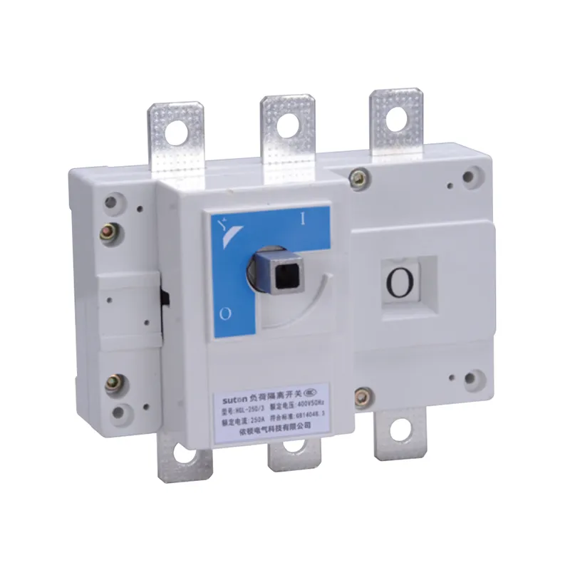
Part 1. Service-isolation role and terminology
The safety-switch request usually concerns a defined service boundary: a machine, feeder, panel section, or nearby equipment that must have an identifiable isolation point before authorized work. Translate the phrase into the single-line, equipment tag, location, access route and operating procedure.
The disconnect switch guide covers broad disconnect procurement. The isolator switch guide covers local isolation terminology, while the main switch guide covers whole-board incomer isolation. This page owns service boundary, visibility, access and recordkeeping.
| Service question | Why it matters | Evidence |
|---|---|---|
| What equipment is isolated? | fixes the boundary | equipment schedule and single-line |
| Who needs access? | defines position and approach | layout and service route |
| What state must be visible? | makes the isolation check repeatable | operating procedure |
| Which device role is intended? | separates isolation from protection | protection and switching schedule |
Part 2. Placement and enclosure interface
Place the switch where the service boundary can be reached and identified without relying on an undocumented remote action. Review panel doors, guards, cable entry, handle clearance, labels, barriers and the route between the isolation point and the equipment it controls.
The public ETGL(HGL) load break switch-disconnector page is a family-level route for a load-break switch-disconnector inquiry. The DZ47-125G miniature switch-disconnector route is a compact switch-disconnector family path. Neither public page replaces the panel GA or the project service procedure.
Part 3. Visible state, access and lock records
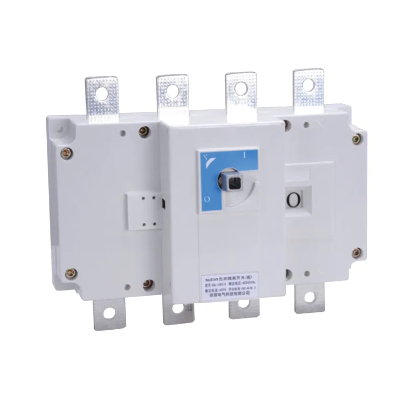
Define what the operator can see, which device tag identifies the boundary, and how the handle or indicator relates to the documented state. Record the normal and isolated positions in the drawing and label schedule. If a lock or seal interface is required, state it as a project input and verify the exact model feature rather than assuming every switch has the same provision.
Keep signage, equipment tag, single-line and service procedure on the same revision. A visible handle does not by itself prove absence of voltage, isolation from every source, or permission to work; those decisions remain with the authorized procedure and design authority.
| Record item | Minimum question |
|---|---|
| Device tag and location | Can the service team identify the correct point? |
| Normal/isolated state | Which position is documented for service? |
| Access and lock interface | What physical control is required and verified? |
| Alternate sources | Are backfeeds or changeover sources addressed? |
| Signage and revision | Can the field record be matched to the drawing? |
Part 4. Verification before service work
Before service work, the authorized procedure should require identification of the correct device, operation of the approved switch, confirmation of the documented state, and any additional verification required by the project. Record the device marking, position, label, revision and responsible person according to that procedure.
Do not present this article as a live-work or lockout instruction. IEC 61439-1 supports the assembly context, while the responsible organization defines the site method. Cableizer technical documentation can help keep circuit and source inputs explicit, but it cannot certify a field isolation result.
Important: A switch position or indicator is not, by itself, proof that every energy source is isolated or that work is authorized. Follow the approved project procedure and hold discrepancies for the design authority (IEC 60947-3).
Part 5. Safety-switch RFQ inputs
Send with the inquiry:
| RFQ input | Why it changes the quote |
|---|---|
| Service boundary and equipment tag | defines what the switch isolates |
| Supply, poles and switching role | fixes the device context |
| Location, enclosure and access limits | checks physical installation |
| Visible-state and label requirements | defines the record and signage package |
| Lock/seal interface requirement | identifies a feature to verify, not assume |
| Alternate sources and backfeed notes | supports the service review |
| Standards, documents and test records | aligns acceptance scope |
| Quantity and accessories | makes quotations comparable |
Attach the single-line, panel GA, service procedure reference, label schedule and controlled revision. A generic “safety switch” request is incomplete if the service boundary and alternate sources are not stated.
Part 6. SUTON route and fit boundary
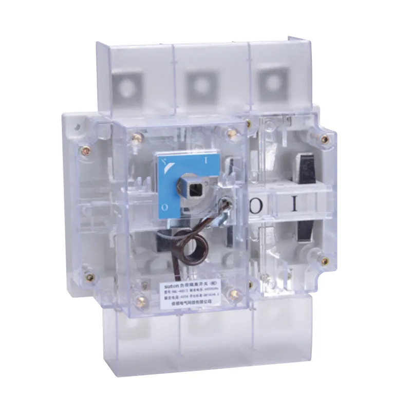
The ETGL(HGL) load break switch-disconnector is a relevant SUTON family route when a service-isolation point needs a documented load-break switch-disconnector path and the project can supply its boundary, location, poles, access and procedure inputs. Review the modular DIN rail products category for adjacent device families.
Fit Boundary: public product pages do not prove a universal safety marking, lock provision, pole arrangement, certification, alternate-source handling or project compliance. If the service boundary, enclosure interface or procedure is incomplete, do not recommend a final model. Route the controlled service-isolation brief to Contact SUTON for model-level review.
FAQ
What is a safety switch?
It is a documented service-isolation point whose boundary, location, visible state, access and operating procedure are defined for authorized work.
Is a safety switch the same as a disconnect or isolator?
The terms can overlap in trade language, but the design must state the service boundary and device role. This page focuses on service documentation rather than a universal label equivalence.
Where should a safety switch be placed?
Place it where the defined equipment boundary can be reached, identified and operated under the approved procedure, with enclosure and handle access shown on the GA.
What should the label and lock record show?
Record the device tag, location, normal and isolated states, service boundary, lock or seal requirement if any, alternate sources and drawing revision.
How should a safety switch be verified?
Use the authorized project procedure to identify the correct device, confirm the documented state and record markings, labels, position, revision and responsible-person evidence.
What should a safety-switch RFQ include?
Send the service boundary, equipment tag, supply and poles, location, enclosure, visible-state, lock/seal, alternate-source, standards, documents, quantity and test-record needs.
When is ETGL(HGL) a relevant route?
Use it as a family-level inquiry route when a load-break switch-disconnector fits the documented service boundary; confirm exact poles, markings, access and project fit with SUTON.