


NO and NC are useful only when the drawing also states the normal condition, the controlled event, and the intended receiving circuit. Treat them as documented contact logic, then verify the selected product’s markings and terminal information before releasing a panel build or quote.
Important: IEC 60947-1 and the released product documentation provide the relevant device context, but they do not turn a generic NO/NC label into an approved wiring instruction. A panel design must define the selected model, contact role, terminal evidence, and verification method.
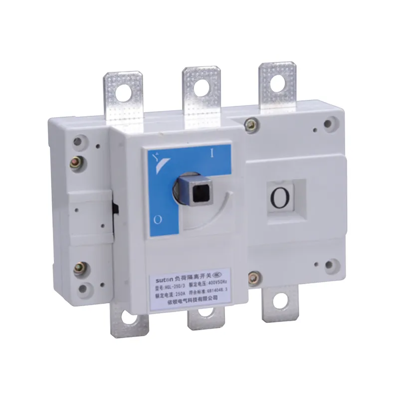
Part 1. Normal-state language for NO and NC
Normally open and normally closed describe the state of a contact under the normal condition defined by the device and drawing. They do not simply mean “off” and “on.” First identify what the host device is doing in its normal state, then define what event changes the contact and what the receiving circuit is expected to see.
This logic is useful for indication, monitoring, interlocking, and other approved control functions. It must be tied to the actual circuit requirement. The auxiliary contact guide explains how status signalling remains distinct from a breaker’s protective function.
| Record field | Question the drawing must answer | Result |
|---|---|---|
| Normal condition | What is the host device doing before the event? | defines the NO/NC reference |
| Controlled event | What movement, command, or status changes the contact? | defines the transition |
| Receiving circuit | Which lamp, PLC input, relay, or monitor receives it? | defines the interface |
| Expected indication | What should the operator observe? | makes the test recordable |
Part 2. Controlled event and drawing logic
Describe the contact by its purpose, not just by the letters NO or NC. For example, the document should identify whether a change is intended to indicate a device position, a specified alarm, or an approved interlock condition. The control schematic, wire identifiers, and terminal schedule should all refer to the same event and device tag.
Do not substitute NO/NC for a full logic description. A contact can look correct in a disconnected drawing yet communicate the wrong state once the host-device sequence, powered condition, or control philosophy is considered. The circuit breaker switch guide provides the adjacent switching-device context without deciding this control logic for a specific project.
Part 3. Contact identity and product-interface evidence
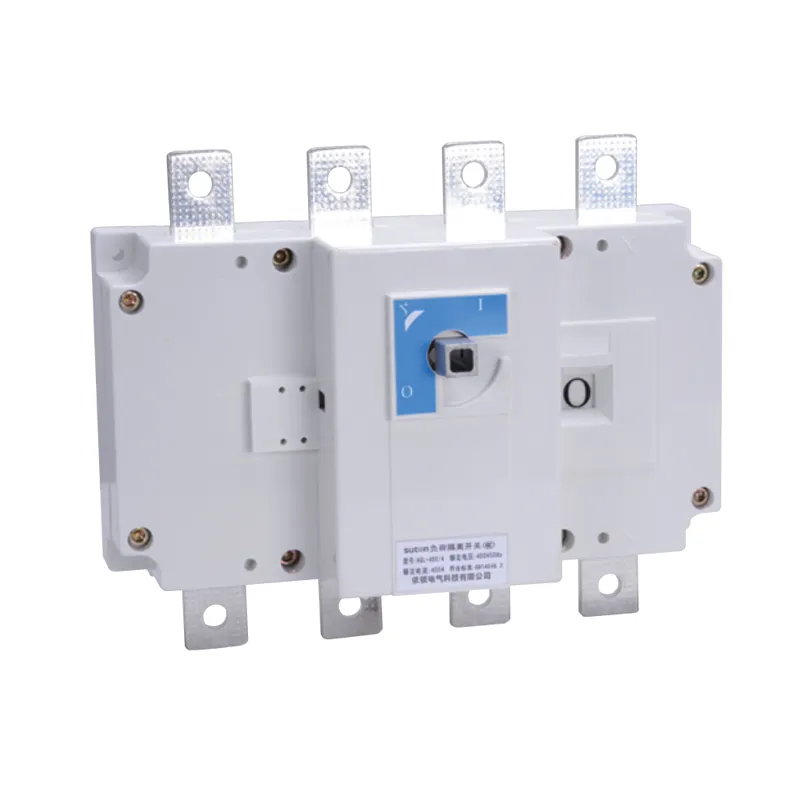
Use the selected product document to verify the accessory code, terminal markings, count of contacts, and permitted arrangement. The public ETGL(HGL) load break switch-disconnector page lists F11 as one normally open and one normally closed auxiliary-contact option, and F22 as two normally open and two normally closed. That public statement supports a family-level inquiry only.
It does not establish a terminal number, load capability, wiring method, accessory combination, or suitability for an interlock or safety function. Capture those limits from the released model document and the approved panel design.
| Evidence to check | Why it cannot be assumed |
|---|---|
| Accessory designation | options vary by selected family and configuration |
| Terminal illustration | labels must match the actual device |
| Contact count and logic | F11/F22 notation must match the required circuit |
| Host-device sequence | changes the meaning of the normal state |
| Installation constraints | control wiring still needs physical access and clearance |
Part 4. Verification records before commissioning
Test the logic only through the authorized project procedure. Compare the released schematic, device tag, terminal label, wire identifiers, normal state, controlled event, and expected receiving-circuit response. Record the document revision and result so the panel can be serviced without reinterpreting the original intent.
Cableizer technical documentation offers vocabulary for structured circuit inputs, but it does not supply a project test result. If the installed markings differ from the drawing, hold the discrepancy for design review rather than changing the state logic in the field.
Important: Do not infer an emergency, protective, isolation, or safety result from an NO/NC label. Verify the approved contact function only, using the selected product information and the project’s commissioning procedure (IEC 60947-1).
Part 5. NO NC switch RFQ inputs
Send with the inquiry:
| RFQ input | Why it matters |
|---|---|
| Host device series and exact configuration | identifies compatible accessory routes |
| Normal condition and controlled event | defines the NO/NC logic |
| Required contact count and role | aligns the interface with the schematic |
| Receiving circuit and control voltage context | supports documentation review |
| Terminal, mounting and access constraints | checks panel-build feasibility |
| Related accessories and restrictions | avoids unsupported combinations |
| Required documents, quantities and test record | makes the response reviewable |
Include the control schematic, terminal schedule, GA, and controlled revision number. A generic “NO/NC switch” line without the normal state and host device is insufficient for a final quotation.
Part 6. ETGL HGL route: contact-option inquiry boundary
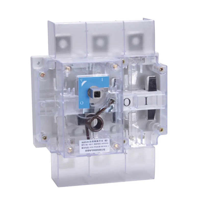
The ETGL(HGL) load break switch-disconnector is a relevant SUTON family route when an approved load-break switch-disconnector arrangement needs auxiliary-contact options and the project can provide the host configuration and control documentation. The modular DIN rail products route provides the upward category context for adjacent panel products.
Fit Boundary: F11/F22 wording on the public page is not a final wiring instruction or a universal contact-duty claim. Do not recommend a terminal route, interlock function, safety application, or final model from the public page alone. Send the schematic, device schedule, normal-state definition, and quantity through Contact SUTON for model-level review.
FAQ
What do NO and NC mean?
They describe the stated contact condition under the defined normal condition. The exact normal condition must be named on the selected device’s drawing and control schematic.
Which state is considered normal?
Normal is the documented reference condition for the host device and control circuit, not a universal synonym for powered, safe, open, or closed.
Is NO/NC the same as on and off?
No. NO/NC describes a contact relationship; on and off describe a device or circuit condition. The drawing must connect the contact transition to the intended event.
How is a contact identified on a control drawing?
Identify the host device tag, accessory designation, terminal labels, wire identifiers, normal state, controlled event, receiving circuit, and expected response.
Why must terminal marking be verified?
Product families and configurations can use different accessories and terminal arrangements. The released model documentation prevents a generic label from becoming an incorrect connection.
How should NO/NC logic be checked before commissioning?
Use the approved procedure to compare device marking, terminal labels, wire identities, normal state, controlled event, receiving response, and drawing revision, then record the result.
What should a NO/NC switch RFQ include?
Provide the host configuration, normal condition, controlled event, contact count, circuit role, terminal and mounting constraints, drawings, required records, and quantity.