


A circuit breaker surge protector request should be split into an SPD decision and an upstream protective-device decision. The SPD addresses the surge-protection concept, while the protective-device arrangement has to match the selected product documentation, network arrangement and approved panel design.
That split matters because no single breaker size, wiring method or installation location applies to every low-voltage project. A panel builder needs project inputs before deciding how an SPD will be incorporated into an assembly.
Part 1. What does the mixed phrase actually describe?
The phrase often joins two components that have different jobs. A surge protective device manages transient overvoltage within a protection concept. A circuit breaker or other upstream protective device may be part of the installation arrangement, but its required characteristics depend on the SPD documentation and the project design.
Treating them as one interchangeable product can lead to a weak RFQ. The better question is: which SPD role is needed at this location, and what protective-device arrangement does the selected product require in the approved assembly?
Part 2. How do SPD and circuit-breaker roles differ?
An SPD is selected around the system’s surge-protection needs and its location in the electrical arrangement. A circuit breaker performs circuit-protection and isolation functions defined by the electrical design. The two can be coordinated in one panel, but a buyer should not assume that a protective device automatically gives an SPD its correct application conditions.
| Item | Primary decision | Evidence needed before selection |
|---|---|---|
| SPD | Surge-protection role and system location | Network arrangement, intended location, selected product documentation |
| Upstream protective device | Protective-device arrangement associated with the selected SPD | SPD manufacturer instructions, prospective fault conditions and approved panel design |
| Earthing and conductor path | Physical integration and surge-current path | Assembly layout, conductor routing and project earthing arrangement |
This distinction also prevents a product comparison from becoming an unsupported promise that a particular combination will satisfy every site requirement.
Part 3. Which location questions shape the surge-protection concept?
Location is more than an empty slot on a DIN rail. The design team needs to identify where the assembly sits in the distribution system, what equipment the arrangement is intended to support and how the required protection concept is documented for that project.
The public Electrical Installation Guide describes SPD selection in relation to the electrical installation and its exposure context. For an RFQ, the useful deliverable is the single-line diagram and the intended installation point, not a generic instruction copied from a different network.
Part 4. Why must upstream protection be checked for the selected SPD?
The upstream protective-device question is product-specific and installation-specific. It should be checked against the current SPD documentation, the approved conductor arrangement and the applicable project rules. Publishing one current value as a universal answer would be misleading because the relevant coordination conditions can vary.
Important: An SPD product route, a current label or a panel photograph is not enough to determine the upstream protective-device arrangement. Confirm the selected SPD documentation and the project electrical design before installation. Source: IEC 61643-11.
Ask the responsible engineer to identify the required protection arrangement before procurement. This keeps the panel builder from assigning a circuit-breaker duty based only on a keyword or a competitor’s wiring example.
Part 5. What should be verified before DIN-rail assembly?
DIN-rail mounting does not eliminate assembly checks. Before installation, confirm the enclosure layout, accessible terminals, separation from incompatible circuits, conductor routing, earthing arrangement and the documentation that governs the selected device.
Do not use this guide as a field wiring procedure. Physical installation and verification must follow the current product instructions, the approved assembly design and applicable local installation requirements. That boundary is especially important when the project includes a lightning-protection concept, external equipment interfaces or site-specific fault conditions.
Part 6. Which procurement situation defines the right RFQ inputs?
The RFQ should describe the electrical context instead of asking for a generic “surge protector breaker.” The following table helps a buyer turn the search phrase into reviewable project information.
| Procurement situation | Decision that must be made | Fit boundary | Buyer should provide |
|---|---|---|---|
| New low-voltage panel | SPD role and assembly location | Not a substitute for the approved system protection design | Single-line diagram, intended installation point, network arrangement and enclosure layout |
| Retrofit in an existing panel | Space, conductor routing and compatibility review | Existing site conditions need verification before change | Existing panel drawings, photos for review, available rail space and current device documentation |
| Equipment protection concern | Which equipment or circuit needs a documented surge-protection concept | A product cannot prove equipment risk has been assessed | Equipment type, circuit relationship, operating environment and project protection objective |
| Distributor quotation request | Product family and documentation route | Final model selection depends on project inputs | Target market, quantity, required documents, system context and engineering contact |
Fit boundary: this guide supports specification and procurement conversations. It does not provide a universal SPD classification, breaker size, wiring diagram, installation approval or site-compliance conclusion.
Part 7. When should a buyer review a SUTON surge-protection route?
For a product-family starting point, review SUTON’s Modular DIN Rail Products category. The related Surge Protector Breaker Guide can help a buyer compare the broader search intent with this installation-focused scope.
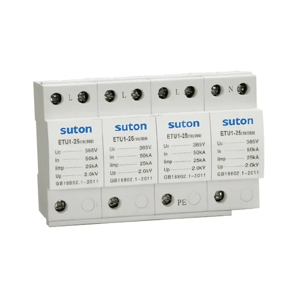
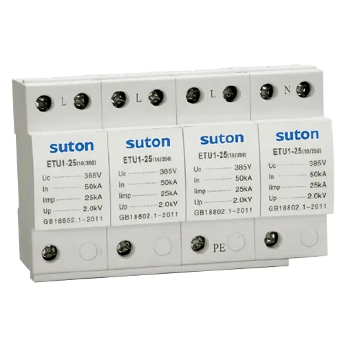
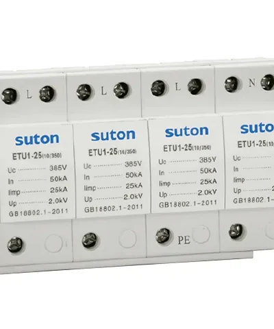
SUTON publishes an ETU1 Series Surge Protective Device route. Request the current applicable data sheet and submit the project inputs before treating a particular model as suitable for a network or protective-device arrangement.
For a quotation review, contact SUTON with the single-line diagram, network arrangement, intended SPD location, required documents and the engineering contact responsible for installation approval.
FAQs
What is a circuit breaker surge protector?
The phrase usually refers to an SPD plus the protective-device arrangement that has to be confirmed for that SPD in a panel. They are related decisions, but they are not the same component or selection task.
Is an SPD the same as a circuit breaker?
No. An SPD addresses transient overvoltage within a surge-protection concept, while a circuit breaker has circuit-protection and isolation duties set by the electrical design.
Where should an SPD be installed?
Its location should be identified in the approved distribution design and evaluated with the system arrangement and the selected product documentation. The correct location is project-specific.
Does an SPD need an upstream circuit breaker?
The upstream protective-device arrangement must be checked against the selected SPD documentation and the project conditions. Do not use a universal breaker size from an unrelated installation as a design decision.
What should be checked before DIN-rail installation?
Check the approved enclosure layout, conductor routing, earthing arrangement, terminal access, separation requirements and the current instructions for the selected product.
What information belongs in an SPD RFQ?
Provide the single-line diagram, network arrangement, intended installation point, enclosure layout, target market, required documents, quantity and the engineering contact responsible for approval.