


A DC circuit breaker decision is a documented duty question — not an AC rating label. DC interruption has no natural current zero crossing to assist arc extinction, so panel builders must use the device’s documented DC ratings, polarity arrangement, and connection conditions before release.
Start with the approved DC single-line diagram. Map the source type, circuit position, fault behavior, isolation boundary, and operating evidence, then compare product routes only against that controlled input set.
Important: This guide structures DC and PV circuit-breaker selection in line with assembly integration practice in IEC 61439-1 and PV system context in IEC 62548-1. It cannot authorize an AC device for DC use or approve interruption duty where source behavior, polarity plan, or fault contribution is missing — hold those inputs for engineering review before procurement.
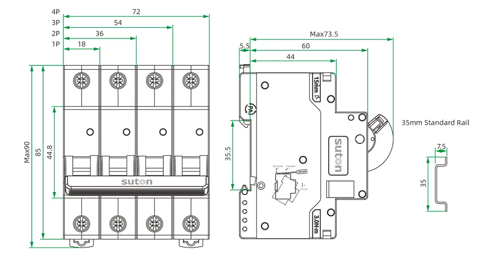
Part 1. Turn a DC circuit breaker request into documented panel inputs
Ask “which DC breaker for this circuit?” and you are asking for a controlled input set tied to a defined system position. Treat a PV string, combiner output, battery circuit, and DC distribution feeder as distinct locations. An AC marking alone is not evidence of suitability for a DC application.
| Selection factor | Why it matters for the panel | Send with quote |
|---|---|---|
| Source type and circuit position | fixes whether the device sees string, combiner, or feeder duty | yes |
| Maximum DC system voltage | fixes insulation and pole arrangement | yes |
| Normal current and prospective fault or backfeed condition | fixes thermal and interruption duty | yes |
| Polarity arrangement and wiring orientation | fixes connection category | yes |
| Isolation requirement and operating procedure | separates protection from maintenance break | yes |
| Enclosure environment and mounting interface | fixes physical duty | yes |
| Standards requested and quantity | fixes approval and procurement batch | yes |
Projects that skip the table often receive quotations built on pole count or nominal current alone. That produces a second procurement cycle once DC performance data, polarity routing, or isolation scope is challenged on site.
Part 2. Map PV and DC system boundaries before device selection
Map the source type, maximum system voltage, normal current, fault or backfeed condition, polarity arrangement, conductor routing, and required isolation point before any catalogue comparison begins. In PV work, distinguish string circuits, combiner outputs, and inverter-side DC circuits.
Review the project against the PV systems route before turning a generic breaker request into an RFQ. Device-level breaker-type context lives in the circuit breaker types guide; this article owns DC boundary mapping, duty inputs, and RFQ structure only.
| DC boundary | Typical protective question | Planning consequence |
|---|---|---|
| PV string circuit | source-limited current and polarity traceability | Do not assume AC MCB equivalence |
| Combiner output | parallel source contribution | Review backfeed and fault contribution |
| Inverter-side DC feeder | higher duty and coordination context | Confirm location-specific fault data |
| Battery or storage circuit | energy contribution and isolation | Separate operating and maintenance boundaries |
Part 3. Record voltage, polarity, and source inputs
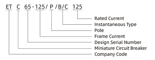
Use the documented DC voltage and pole arrangement at the proposed location. Confirm any required polarity marking, series-pole arrangement, and wiring orientation from the exact product documentation. A two-pole diagram does not prove every device can be wired in every DC configuration.
Record parallel sources, energy-storage contribution, and any condition where fault current may exceed the string-limited case alone. If the source behavior is incomplete, preserve the uncertainty in the RFQ rather than converting an assumption into a purchase specification.
Reserve module positions, terminal orientation, bending space, and labeling access from the schematic before the enclosure layout is frozen.
Part 4. Review interruption duty and coordination evidence
Record the available DC source behavior, prospective current, parallel sources, and any energy-storage contribution. Compare the required duty with the exact product’s DC performance data and application conditions.
Do not transfer AC interrupting data or AC curve language into a PV or DC selection without specific evidence. A nominal-current match does not prove DC suitability, and a familiar module width does not prove the approved wiring orientation.
Where upstream or downstream devices share a protective path, retain manufacturer combination data or test references with the panel dossier. Later service and expansion work should still trace back to the installed markings on those records.
Part 5. Separate isolation from protection at each boundary
A project may require both overcurrent protection and a defined isolation function at different boundaries. Follow the approved one-line diagram and operating procedure for each. Labels, lockout provisions, and accessible isolation points are assembly requirements, not optional accessories.
Do not treat a protective device as proof of a maintenance isolation function unless the exact configuration and project evidence establish it. Record the authorized operating sequence and the circuit identity that each boundary serves.
Before energization, verify terminal assignments, polarity marking, conductor terminations, circuit identification, and approved test access against the released drawing.
Part 6. Route an evidence-based SUTON inquiry
Send with the inquiry:
| RFQ input | Why it matters |
|---|---|
| DC one-line diagram with circuit positions marked | shows where protection and isolation are required |
| Source type, maximum voltage, and normal current | fixes electrical duty |
| Prospective fault or backfeed behavior | fixes interruption review |
| Polarity plan and approved wiring orientation | fixes connection category |
| Isolation requirement and enclosure environment | fixes assembly and operating scope |
| Standards requested, accessories, and quantity | fixes approval and procurement batch |
Require suppliers to declare the exact offered marking, DC performance data, installation instructions, accessories, and exceptions against the controlled documents. Hold the engineering decision when source behavior or circuit position is incomplete — a quotation against an undefined DC boundary cannot preserve the design intent.
Fit Boundary: this guide structures PV and DC decision inputs for panel builders. It does not authorize an AC device for DC use, does not replace a system study, and cannot select a breaker from an amp rating alone where source contribution or polarity routing is unknown. Escalate those gaps to the design authority before the package is priced.
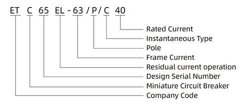
Start with SUTON’s PV systems route and send the DC single-line diagram and operating data through Contact SUTON. Confirm every proposed product’s DC voltage, current, pole arrangement, wiring orientation, and interruption data from its current datasheet before release. Hold each quotation to the same DC duty worksheet and archive the approved version with the PV dossier.
PV dossier and service discipline
Treat the DC single-line diagram, circuit schedule, polarity plan, coordination references, test records, and revision history as one handover package. Facilities that inherit the dossier can maintain and expand the DC system with traceability; facilities that inherit only a breaker label tend to rebuild the review from scratch at the first fault event.
When strings, combiners, or storage circuits are added, update the diagram and duty worksheet before re-energizing. A new parallel source can change interruption duty even when nominal current appears unchanged.
After any abnormal operation, record the circuit position, source state, connected loads, and recent switching activity before changing a rating or replacing a device.
FAQ
Why can a DC circuit breaker not be selected from AC data alone?
DC interruption and connection conditions require the exact product’s documented DC ratings and instructions.
What PV boundary data is needed?
Identify the string, combiner, or inverter-side location, source type, maximum voltage, current, polarity, and isolation requirement.
Does pole count prove DC suitability?
No. Verify the exact pole arrangement, polarity marking, and approved wiring orientation in product documentation.
What does a DC breaker RFQ need?
Provide the DC one-line diagram, source behavior, voltage, current, polarity plan, circuit position, environment, and quantity.
Can AC tripping claims be reused for PV selection?
No. Use only documented DC performance data applicable to the proposed PV or DC circuit.
When is engineering review required?
Escalate unknown source contribution, parallel sources, battery interaction, unverified interruption duty, or unclear isolation boundaries.